2-52
2-2 External and Mounting Hole Dimensions
2
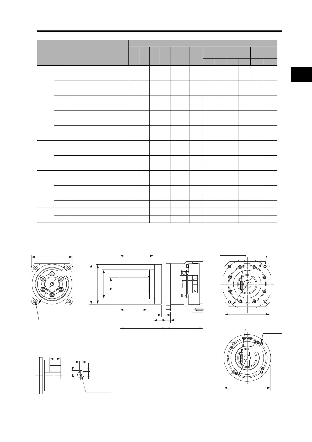
Standard Models and Dimensions
*1. This is the set bolt.
Outline Drawings
*2. With the R88G-HPG50, the height tolerance is 8 mm (D3 dia., h: 8).
Model
Dimensions (mm)
G S T Z1 Z2 AT
*1
Key dimensions
Tap
dimensions
QK b h t1 M L
1 kW
1/5 R88G-HPG32A051K0B 13 40 8211M612 M6 70 12 8 5.0 M10 20
1/11 R88G-HPG32A111K0B 13 40 8211M612 M6 70 12 8 5.0 M10 20
1/21 R88G-HPG32A211K0B 13 40 8211M612 M6 70 12 8 5.0 M10 20
1/33 R88G-HPG32A331K0B 13 40 8211M612 M6 70 12 8 5.0 M10 20
1/45 R88G-HPG50A451K0B 16 50 8214M610 M6 70 14 9 5.5 M10 20
1.5 kW
1/5 R88G-HPG32A052K0B 13 40 8211M810 M6 70 12 8 5.0 M10 20
1/11 R88G-HPG32A112K0B 13 40 8211M810 M6 70 12 8 5.0 M10 20
1/21 R88G-HPG32A211K5B 13 40 8211M810 M6 70 12 8 5.0 M10 20
1/33 R88G-HPG50A332K0B 16 50 8214M810 M6 70 14 9 5.5 M10 20
1/45
R88G-HPG50A451K5B 16 50 8214M810 M6 70 14 9 5.5 M10 20
2 kW
1/5 R88G-HPG32A052K0B 13 40 8211M810 M6 70 12 8 5.0 M10 20
1/11 R88G-HPG32A112K0B 13 40 8211M810 M6 70 12 8 5.0 M10 20
1/21 R88G-HPG50A212K0B 16 50 8214M810 M6 70 14 9 5.5 M10 20
1/33 R88G-HPG50A332K0B 16 50 8214M810 M6 70 14 9 5.5 M10 20
3 kW
1/5 R88G-HPG32A053K0B 13 40 8211M818 M6 70 12 8 5.0 M10 20
1/11 R88G-HPG50A113K0B 16 50 8214M816 M6 70 14 9 5.5 M10 20
1/21 R88G-HPG50A213K0B 16 50 8214M816 M6 70 14 9 5.5 M10 20
4 kW
1/5 R88G-HPG32A054K0B 13 40 8211M825 M6 70 12 8 5.
0 M10 20
1/11 R88G-HPG50A115K0B 16 50 8214M825 M6 70 14 9 5.5 M10 20
5 kW
1/5 R88G-HPG50A055K0B 16 50 8214M825 M6 70 14 9 5.5 M10 20
1/11 R88G-HPG50A115K0B 16 50 8214M825 M6 70 14 9 5.5 M10 20
S dia.,h: 7
D5 dia.
D4 dia.
D3 dia., h: 7
*2
Four, Z2
Set bolt (AT)
C2 dia.
C1 × C1
Four, Z1 dia.
C2 × C2
Four, Z2
Set bolt (AT)
E
T
F1
F2
LR
G
LM
D2 dia.
D2 dia.
D1 dia.
QK
Key and Tap Dimensions
b
h
t1
M (depth: L)

 Loading...


