CRC code is used for checking the error in message frame during data transmission. Transmit
side adds CRC code to message frame after calculation. Receive side also calculates CRC code
of the received data. Then the two CRC codes are verified.
CRC code is CRC-16(CRC-ANSI). It is determined and calculated by the right feed of HA001.
(x
16
+x
15
+x
2
+1)
・ When the CRC code of received data is not correct, no processing is carried out and no
response data is sent.
[CRC code]
・ When the CRC code of received data is H00, no CRC check is performed.
The response data is sent back with the calculated CRC code.
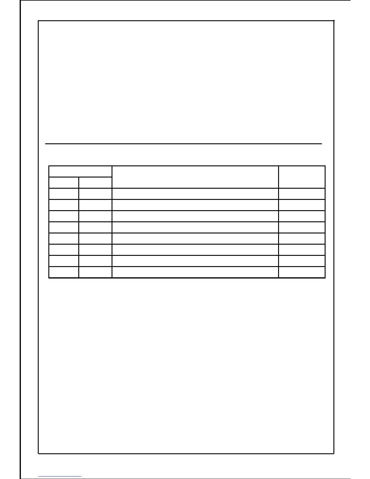
12-7. Function code for MOD-BUS (RTU) in inverter
The inverter is supported for the following eight codes.
Write Multiple Registers
Write Multiple Coils
Write Single Register
Write Single Coil
Read Input Registers
Read Holding Registers
Read Discrete Inputs
Read Coils
Name
16
15
06
05
04
03
02
01
DEC
Function code
32 registersH10
32 coilsH0F
1 registerH06
1 coilH05
32 registersH04
32 registersH03
32 coilsH02
32 coilsH01
HEX
Maximum
number
of read/write
・ There is no distinction between Coil (Discrete output) and Discrete input, nor between Input
register and Holding register.
173