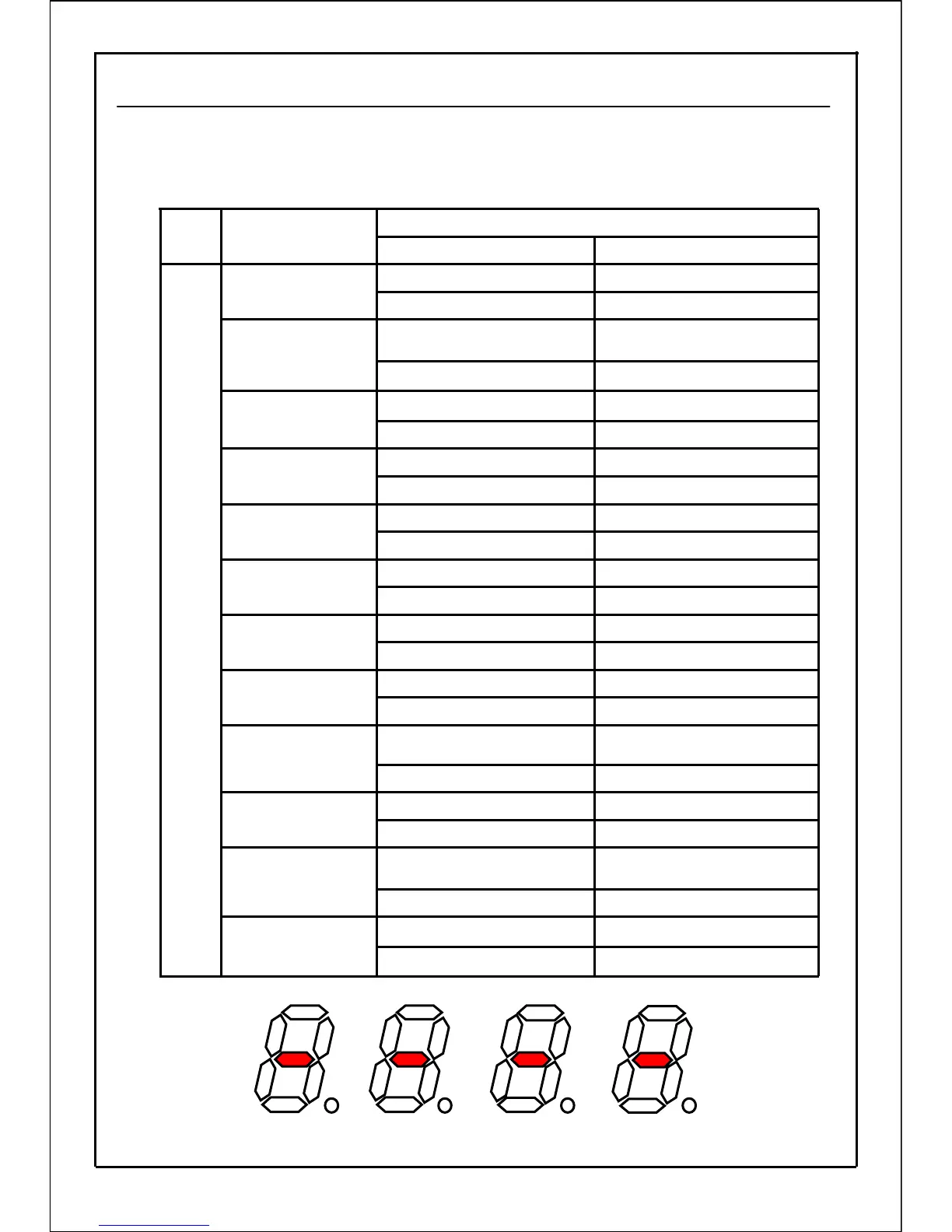
n011:Operation state monitor
Indicates operation state of the inverter. Each LED segment lights and lights out according
to the details of lighting and lighting out shown in the following table.
Normally, segment data i ~ I light.
c1 lights outc1 lights
Normal operation state
Automatic tuning function
of motor constant
Automatic tuning
function of motor
constant
Normal stateError state
Normal operation stateTimer operation state
Timer operation
function
b1 lights outb1 lights
OFF stateON state
Detect current
(or more) signal
g lights outg lights
d lights outd lights
OFF stateON state
OFF stateON state
Overload signal
b lights outb lights
LED segment indication
Operation state
Monitor
No.
a lights outa lights
f lights outf lights
OFF stateON state
Detect current
(or less) signal
h lights outh lights
Normal operation state
PID automatic tuning
operation state
PID automatic
tuning function
a1 lights outa1 lights
d1 lights outd1 lights
Error state
OFF stateON state
Frequency detect
(parameter P094)
e lights oute lights
Frequency detect
(parameter P093)
c lights outc lights
OFF stateON state
Arrival signal
Stop state or forward
run operation state
Reverse run operation state
Reverse run
operation state
Stop stateOperation state
Operation state
n011
Details of lighting outDetails of lighting
a
c
e
g
b
d
f
a1
c1
g1
b1
d1
f1
e1
h
h1
i
j
k
l
49