MODE button
Frequency
setting dial
SET button
FWD display
REV display
RUN button
STOP button
Main display
▲(UP) button
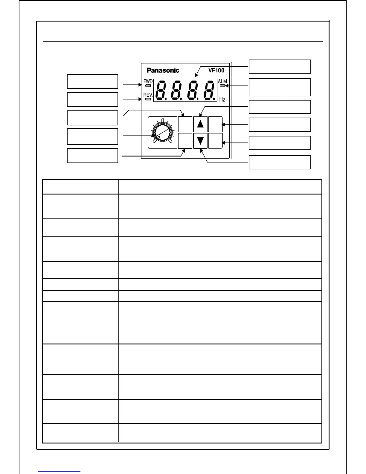
Alarm display
(ALM)
Errors and alarm are displayed.
(Refer to P147: Alarm LED operation selection)
Alarm display (red)
Reverse run is displayed (During operation at constant speed:
Lamp will turn ON; During acceleration/deceleration operation:
flicker).
REV display (green)
Description of Functions Name of Each Part
Forward run is displayed (During operation at constant speed: Lamp
will turn ON; During acceleration/deceleration operation: flicker).
FWD display (green)
This is the dial for the potentiometer used to set the operating
frequency with operation panel.
Frequency setting dial
This switch is used to change the data and output frequency, and
to set reverse run direction when carrying out reverse rotation
with the operation panel.
(DOWN) button
This switch is used to change the data and output frequency, and
to set forward run direction when carrying out forward rotation
with the operation panel.
▲(UP) button
The switch is used to change the display between the mode and
data display, and to save the data. In the "operation status display
mode", this switch changes the display between the frequency
and current.
SET button
This switch is used to change to each "operation status display",
"frequency setting, monitor", "rotation direction setting", "control
status monitor", "custom", "function setting", and "built-in memory
setting" mode, and to switch the display from the data to mode
display.
MODE button
The switch is used to stop the inverter.STOP button
The switch is used to start the inverter.RUN button
The output frequency, current, line speed, setting frequency,
communication station No., error details, each mode display
and data for function setting are displayed.
Main display
▲(DOWN) button
19
5-5. Explanation of Operation Panel
MODE
SET
MIN.
MAX.
RUN
STOP