○
○
○
Changeable
during
operation
0~120.0
0.5~60.0
0~100
0~120.0
0.5~60.0
0.5~60.0
0・1
0・1
0.1~100.0
0~2
0~3
1~10
0~3
1~200
0~9.9
0・1
0・1
0.1~100.0
0~3
0~2
0~500
0~100
5~400.0
0~100
0.5~400.0
45.0~400.0
50.0~400.0
0~40
0・1
50・60・FF・3C
0~7
0~7
0000, 0.1~3600
0000, 0.1~3600
Setting range
0.1SWait timeP026
0
-
Ride-through restart selectP025
1
-
Start modeP024
1timesRetry timesP023
0.5HzStart frequency
P029
0
-
Stop modeP028
0
-
Reverse run lockP027
0.5HzStop frequencyP030
0
S
DC brake timeP031
0
%DC brake levelP032
0.5Hz
Stop frequency during forward
/reverse operation
P033
S
-
%
S
-
-
A
-
-
V
%
Hz
%
Hz
Hz
Hz
%
-
-
-
-
S
S
Unit
Remarks
0
0
140
0
1
1
*
2
0
0
0
0.5
00
0.5
50.0
50.0
4
0
50
0
0
5.0
5.0
Initial
value
Overvoltage stall prevention
Function
P019
Current limit functionP020
OCS levelP021
Retry functionP022
DC brake time during forward
/reverse run operation
P034
Overcurrent stall prevention
function
P018
Thermal current settingP017
Electronic thermal selectP016
S-shaped acceleration/
deceleration mode
P015
Max. output voltageP014
Change point voltage 2P013
Change point frequency 2P012
Change point voltage 1P011
Change point frequency 1P010
Base frequencyP009
Max. output frequencyP008
Torque boost levelP007
V/F curveP006
V/F patternP005
Frequency setting signalP004
Operation command selectP003
1
st
deceleration time
P002
62
62
63
64
65
67
68
69
69
70
70
70
70
71
71
72
72
73
73
74
74
75
75
76
77
78
79
79
79
79
80
80
80
80
1
st
acceleration timeP001
Reference
page
Function nameNo.
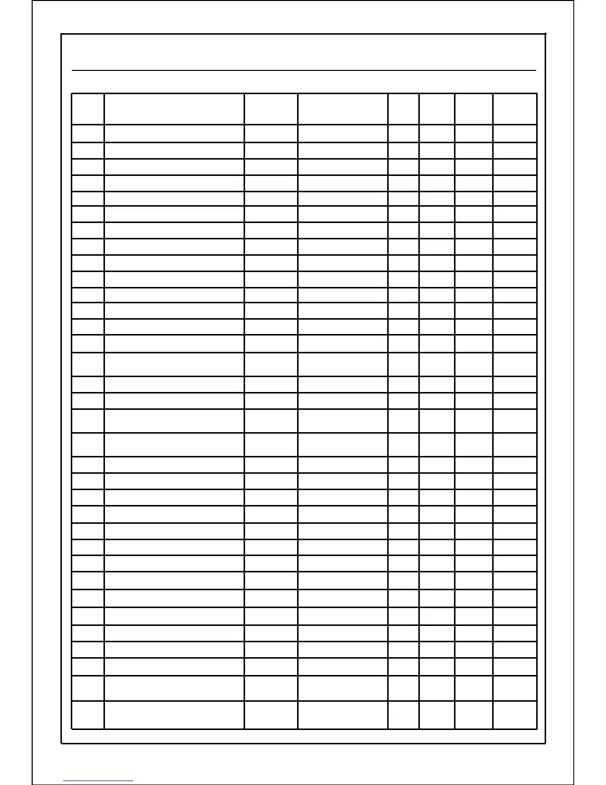
Function parameters of inverter VF100 are shown in the following table.
57
9-2 Functional Descriptions (Parameters Table)