P036~P040
Related
parameters
P041: Input logic setting
It can be selected to detect the input signal by "A contact input" or "B contact input".
<Setting value>
・ A contact input="0": When SW(switch) signal is closed (terminal level is "L"), ON is detected.
・ B contact input="1": When SW(switch) signal is opened (terminal level is "H"), ON is detected.
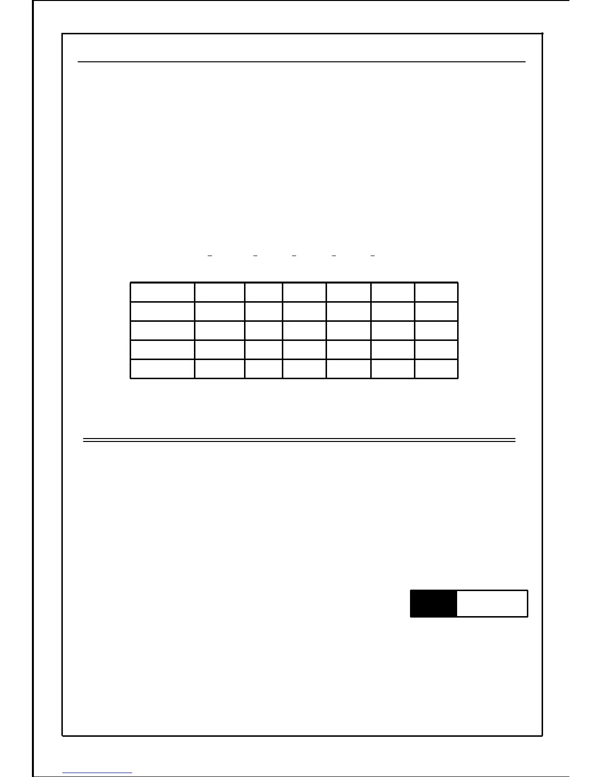
<Setting method>
・ Convert 0 to 4 bits to decimal numbers and input.
・ Input the total value of the setting value × the additional value into the setting data.
124816-
Additional
value
0 / 10 / 10 / 10 / 10 / 10 / 1
Setting value
012345-15bit
④⑤⑥⑦⑧
-Terminal No.
SW1SW2SW3SW4SW5
Without
setting
Terminal
name
[Example] When SW1 and SW2 are B contact input, and other signals are A contact input
Setting data=(0×16)+(0×8)+(0×4)+(1×2)+(1×1)=3
・ ON-OFF state of each SW changes according to the input logic setting. Completely confirm
the setting value before using each terminal.
・ Forward run/reverse run and run/stop are always A contact input.
・ When each SW function is set to "3-wire stop command function", "B contact input" is always
applied even if the input logic setting is set to "A contact input."
Note
89