P092Relay contact output terminal (COM)C
P092Relay contact output terminal (NC: at factory setting)B
P092Relay contact output terminal (NO: at factory setting)A
-Unused terminal
P135-142RS485 communication terminator terminal (E)
P135-142RS485 communication transmission line - terminal (D-)
P135-142RS485 communication transmission line + terminal (D+)
P135-142RS485 communication transmission line - terminal (D-)
P135-142RS485 communication transmission line + terminal (D+)
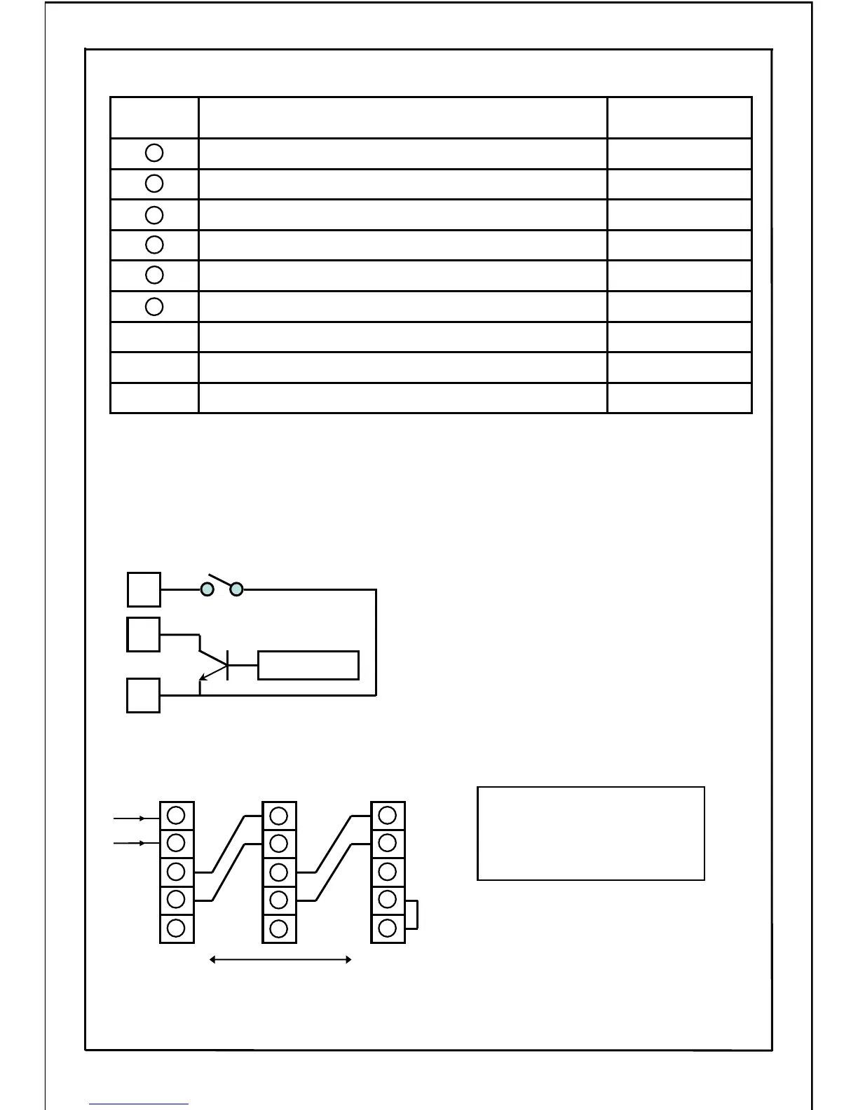
■ Explanation of Control Circuit Terminals
21
19
20
22
23
24
19
20
21
22
23
19
20
21
22
23
19
20
21
22
23
◆PWM signal can be used to control the operating frequency with terminals 7 and 8.
・No.7: Frequency setting signal changeover input terminal (SW4)
(OFF: PWM signal, ON: Controlled with signal set in parameter P004)
・No.8: PWM signal input terminal
Note 1) When using PWM signal to control output
frequency, P087 to P089 must be set.
Note 2) Use a PWM signal transistor (Tr) that has
the following capabilities:
・Max. rated voltage: 50VDC or more
・Rated current: 50mA or more
7
PWM signal
SW4
Tr
8
9
D+ : Transmission line + terminal
(RS485 communication)
D-
: Transmission line - terminal
(RS485 communication)
E
: Terminator terminal
(RS485 communication)
* Connect the D+ side and D+ side, D- side
and D- side of the communication terminals.
* The D- side and E side of the inverter to be
a terminator should be shorted. Do not short
the units other than the terminator.
◆Terminals to connect personal computers and PLCs by the RS485 communication.
Terminator
D+
D−
D+
D−
D−
D+
D+
D−
E
D+
D−
D+
D−
Short
-circuit
Transition connecting wire: Max. 500m
RS485
24
Related Parameter
No.
Terminal Function
Terminal
No.