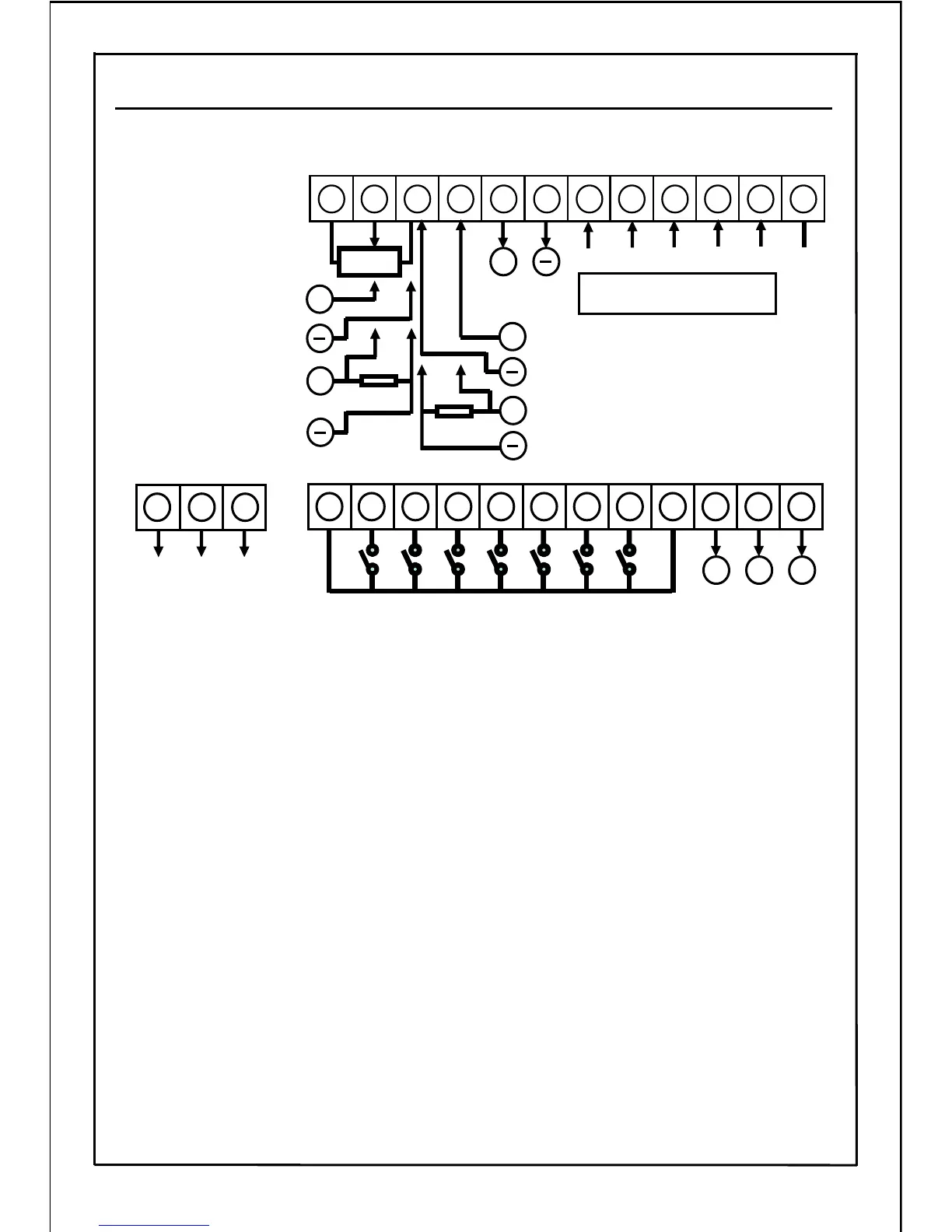
■ Wiring(Control Circuit Terminal)
Start
/
Stop
(Common)
(Common)
0〜5V
0〜10V
4~20mA
1 2 3 4 5 6 7 8 9 10 11 12
(Common)
(Common)
SW1 SW2 SW3 SW4 SW5
Open collector output
(TR1、TR2)
C1 C2
E
13 14 15 16 17 18 19 20 21 22 23 24
+
200
Ω
VR
+
Analog output
(0~10V)
+
200
Ω
+
+
0〜5V
0〜10V
4~20mA
0~20mA
0~20mA
D+
D-
D+
D- E
RS485
communication terminal
Unused
COMNCNO
Relay output
CBA
◆Frequency setting potentiometer(VR) specifications: 10 kΩ, 1/4W or more
◆Relay output contact specifications: 1c no-voltage contact,
230V AC 0.3 A and 30V DC 0.3A (Resistance load)
◆Open collector output specifications: Maximum rating 50V DC,50mA
【Wiring Method】
・
For the wiring of the control circuit terminals, use the electric wires after removing
the specific size of wire's insulation.
・
Loosening the terminal screws and insert the wires from under the terminal block,
and tighten the screws to the designated tightening torque.
Note 1) Twist the strands of the uncovered electric wires.
Do not solder them.
Note 2) Tightening loosely causes the wires to be come away or malfunctions.
Tightening too hard causes the short-circuit due to the damage of the screw
or the inverter.
Note 3) When using 4~20mA or 0~20mA signal in frequency setting, always connect
the resistor(200Ω, 1/4W). (Otherwise, the inverter may be broken.)
Note 4) Please read carefully the specific functions of relevant parameters of each terminal
before attempting to operate the inverter.
Note 5) Common terminals(①,⑨, ⑮, ⑱) are connected within the inverter.
Do not ground the common terminal.
22
6-2. Wiring (Control circuit)
Forward
/
Reverse