Wiring
Operating Manual PMCprotego D.48, PMCprotego D.72
1001735-EN-04
111
6.6.3 Motor holding brake
DANGER!
Risk from non-safety-related activation of the motor holding brake!
Activation of a holding brake via output BR+/BR- of the servo amplifier is not
safety-related. Depending on the application, hazardous motor movements
may cause serious injury or death.
A motor holding brake activated by the servo amplifier alone is not suitable
for personal protection.
Block the drive through an additional mechanical holding brake, which is ac-
tivated safely (e.g. with the safety card PMCprotego S1-2).
Under “Connection cables”, please note the requirements for the:
} Cable cross sections
} Insulation material
Connector X9A Pin Designation Description
1 BR+ Brake+
2 BR- Brake-
Connector pin assignment
Connector X9B Pin Designation Description
1 BR+24V Supply voltage 24 V for motor hold-
ing brake
2 BRGND Earth
Connector pin assignment
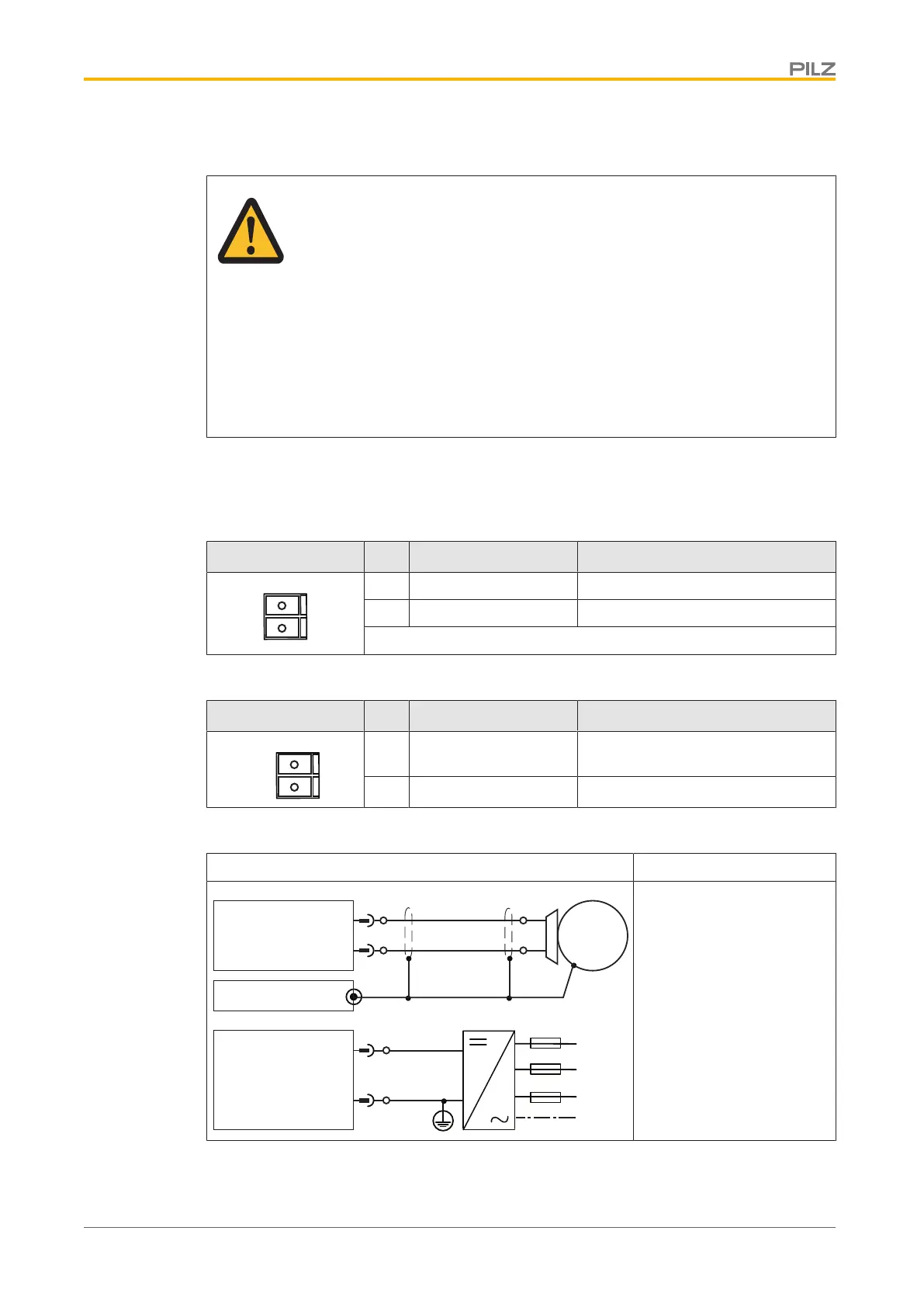
Output circuit Motor holding brake
1
2
PMCprotego
X9A
BR+
BR-
M
BR +24 V
BRGND
X9B
L1
L3
L2
PE
1
2
Wires to the brake (BR+/
BR-) should be shielded
Connect the shielding on
both ends
Connection
 Loading...