Once the servo amplifier is switched on you will have access to the status, error and warn-
ing messages via the standard menu.
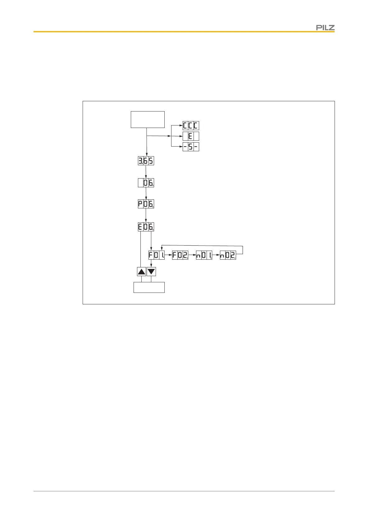
The diagram below shows how the display is structured.
Switch on
24 V
Problem accessing memory card
Reads data from EnDat
Input STO-ENABLE = 0 V
Status 1: 24 V switched on
Device signals version of base software
After 1 s switch to status 2, 3 or 4
Status 1: 24 V
Status 2: 24 V switched on
Device signals current coding (6 A)
Point flashes
Status 3: 24 V and mains voltage switched on
Device signals current coding and
mains voltage, point flashes
Status 4: 24 V and mains voltage switched on
Device signals current coding, power on
and ENABLE. Point flashes
Errors or warnings are displayed
consecutively for 4 flash cycles each
Parameter
 Loading...