Wiring
Operating Manual PMCprotego D.48, PMCprotego D.72
1001735-EN-04
162
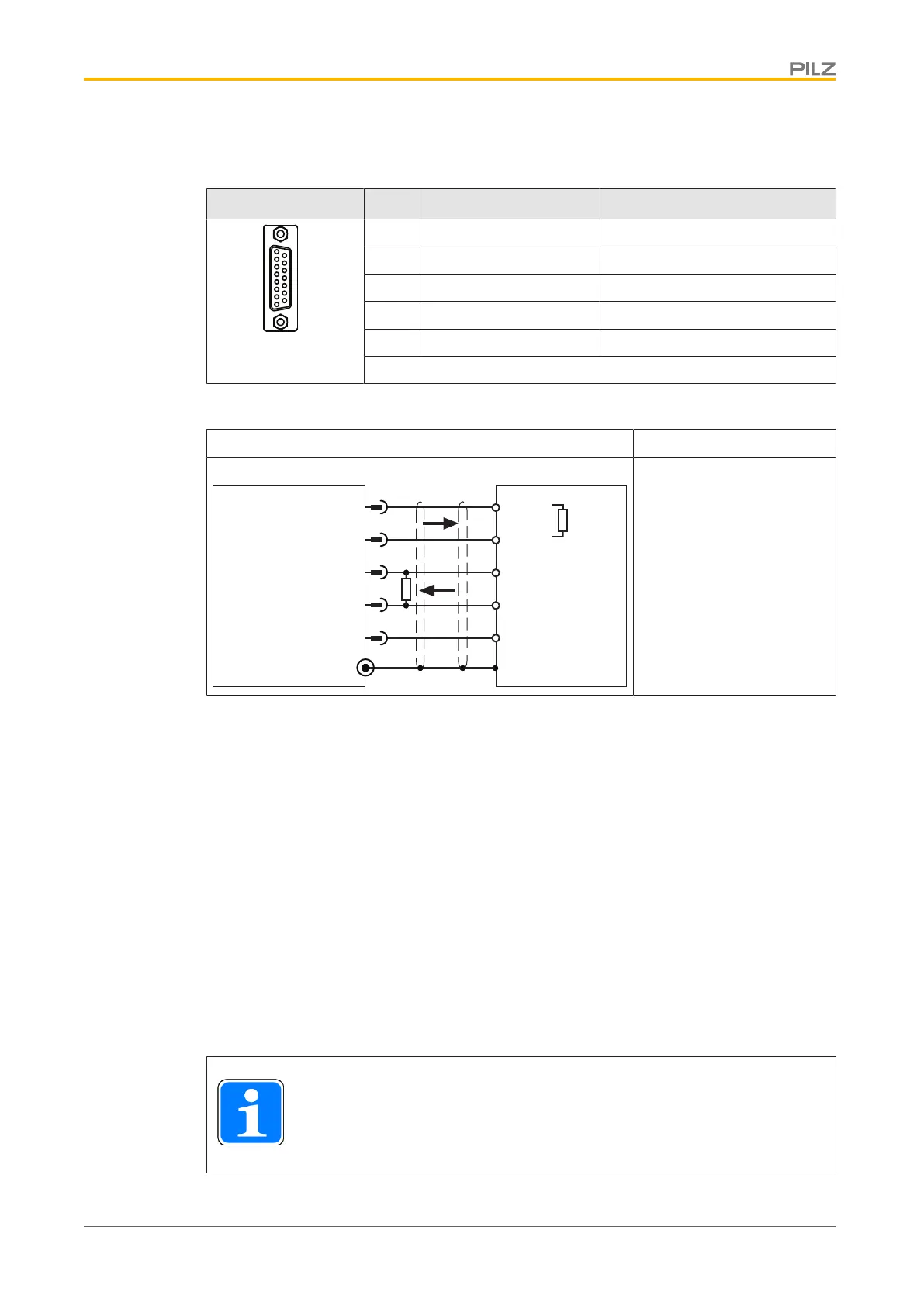
Output of SSI signals
Connector X1 Pin Designation Description
2 GND Ground
5 DATA Data
8 CLOCK Pulse signal
13 DATA\ Data inverted
15 CLOCK Pulse signal inverted
Connector pin assignment
Output circuit Output of SSI signals
5
13
2
PMCprotego
X1
PLC
8
CLOCK
CLOCK\
DATA
DATA\
GND
15
GND
CLOCK
CLOCK\
DATA
DATA\
R
T
R
T
Shield connection in the
connector
Always connect GND to the
earth on the control system
Select RT in accordance
with the cable impedance,
typically 150Ω
Connection
6.7.6 Communications interfaces
6.7.6.1 RS 232 interface
We recommend shielded cable for the RS 232 interface.
If you use unshielded cables, the interface may malfunction.
} Earth the cable shielding on both sides (e.g. on a bus bar).
} Transient currents can be anticipated on longer cables. If this is the case you should
use equipotential bonding cables.
} With the supply voltages switched off, connect the interface (X6) on the servo amplifier
to a serial interface on the PC via a null modem cable.
INFORMATION
Do not use a null modem link cable!
 Loading...