Function Description
Operating Manual PMCprotego D.48, PMCprotego D.72
1001735-EN-04
38
4.2.6 Intermediate circuit topology
Information on fuses, depending on the device type, can be found in chapter Mains
voltage [ 108].
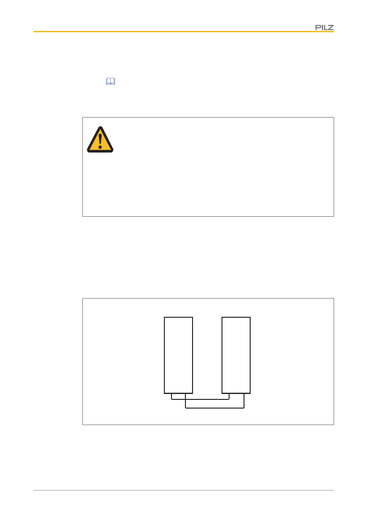
Intermediate circuit connection
CAUTION!
Servo amplifiers could be destroyed
Make sure that the devices are connected only with the supply voltage from
the same supply (voltage and phases) on the intermediate circuit. Other-
wise, high voltage differences on connected intermediate circuits could des-
troy the servo amplifiers.
The VBUSBAL setting must be identical with all the devices involved.
The sum of the all the nominal currents switched in parallel to a PMCprot-
ego D48 servo amplifier must not exceed 96 A.
} Use unshielded single wires with a length of max. 500 mm (conductor cross section 25
mm
2
).
Use shielded cables for larger cable lengths.
} Amplifiers that frequently work as generators in the application should be placed next to
devices that frequently consume energy. This reduces the current flow over longer dis-
tances.
DC DC
PMCprotego D48
PMCprotego D48
Fig.: Intermediate circuit connection
 Loading...