Wiring
Operating Manual PMCprotego D.48, PMCprotego D.72
1001735-EN-04
159
6.7.5.19 Electronic gearing, Master-Slave mode
Connection to a stepper motor control system with 5 V signal
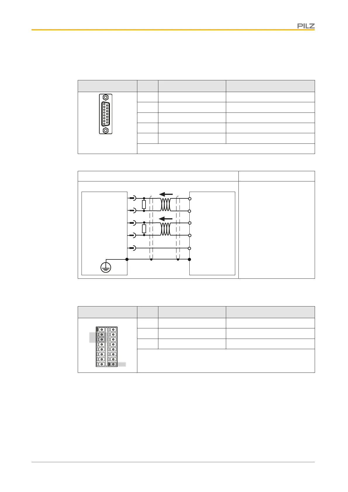
Connector X1 Pin Designation Description
2 0 V Supply voltage 0 V
5 DIR+ Direction
8 PULS+ Pulse
13 DIR- Direction inverted
15 PULS- Pulse inverted
Connector pin assignment
Input circuit Pulse/direction encoder 5 V
8
15
13
Servo Drive
X1
5
2
R
T
Master
PULS+
PULS-
DIR+
DIR-
GND
PULS+
PULS-
DIR+
DIR-
0 V
R
T
Twisted pair, shielded
Shield connection in the
connector
Terminating resistor R
T
=
120 Ohm
Connection
Connection to a stepper motor control system with 24 V signal
Connector X3 Pin Designation Description
X3A
1
2
3
4
X3B
5
6
7
8
9
10
12
13
14
15
16
11
2 DIGITAL-IN1 Input for direction
3 DIGITAL-IN2 Input for pulse
16 DGND Reference earth for digital inputs
Connector pin assignment
 Loading...