Wiring
Operating Manual PMCprotego D.48, PMCprotego D.72
1001735-EN-04
164
6.7.6.2 CANopen interface
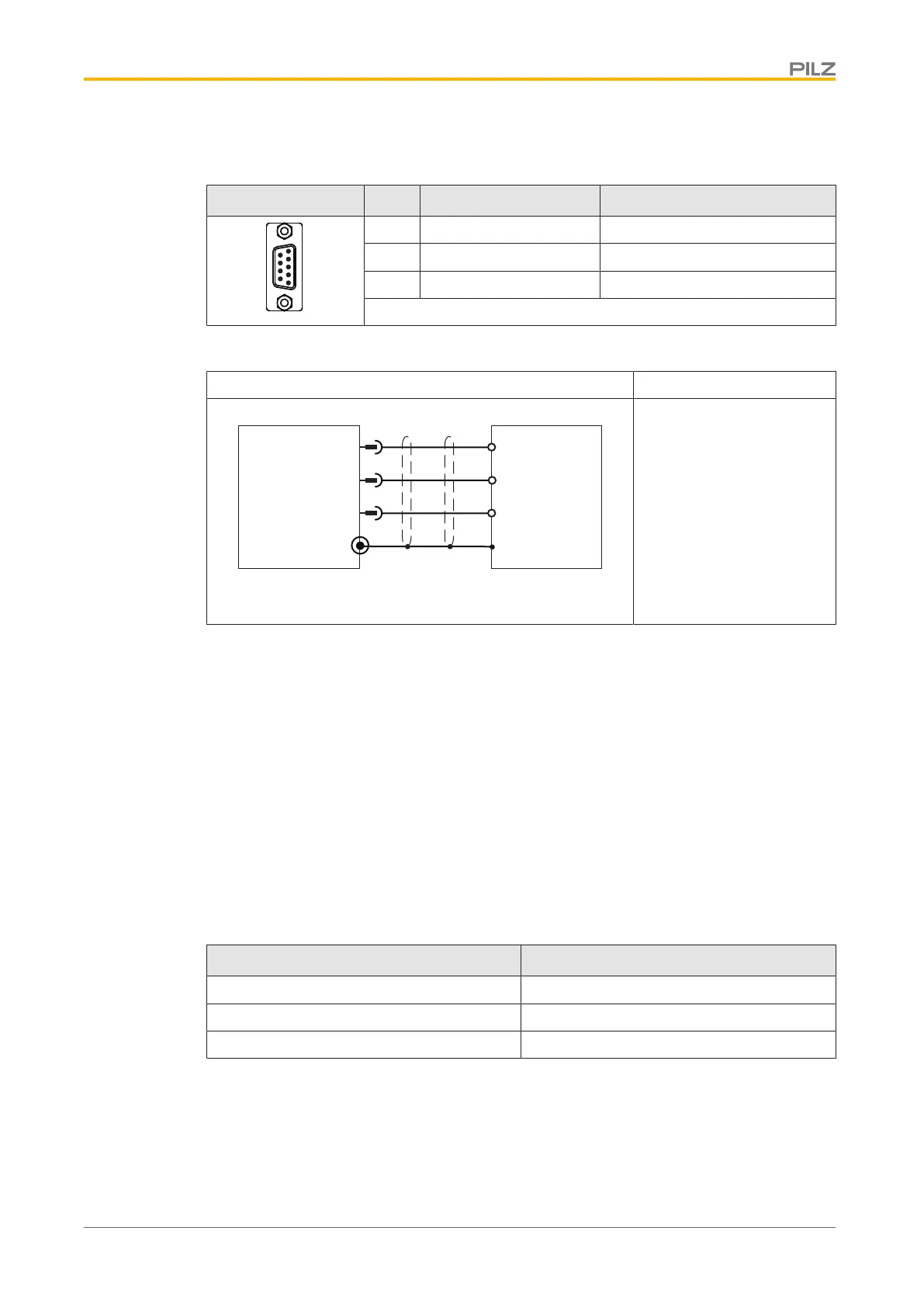
Connector X6 Pin Designation Description
5 CAN_GND Ground
6 CAN_L CAN low signal
9 CAN_H CAN high signal
Connector pin assignment
Port CANopen
CAN_H
9
6
Servo Drive
X6
CAN_L
CANopen Server/Client
5
CAN_GND
CAN_H
CAN_L
CAN_GND
Shielded cable
The interface is on the
same connector as the
RS232 interface.
The RS232 and CANopen
interface use the same op-
erating earth (GND).
Connection
The CANopen specification CiA DS-301 V4.0 requires the cable at both the start and end of
the bus to be terminated with a resistor (120 Ohm, 5% metal film, 1/4 Watt).
The terminating resistor is usually integrated within the connector and can be activated
there.
The cable runs for reliable communication decrease as the transmission rate is increased.
The following values can be used as a guide, but they should not be regarded as limit val-
ues:
Cable data:
} Characteristic impedance 100 - 120Ω
} Operating capacitance max. 60 nF/km
} Cable resistance (loop) 159.8Ω/km
Transmission rate [kBit/s] Max. cable runs [m]
1000 10
500 70
250 115
Cable runs in relation to transmission rate
Longer cable runs can be achieved with lower cable capacitance (max. 30nF/km) and
lower conductor resistance (loop, 115Ω/km).
Characteristic impedance 150 ± 5Ω => terminating resistor 150 ± 5Ω.
For EMC reasons, the D-Sub connector housing must meet the following requirements:
 Loading...