Function Description
Operating Manual PMCprotego D.48, PMCprotego D.72
1001735-EN-04
67
Position
Bit 15 14 13 12 11 10 9 8 7 6 5 4 3 2 1 0
Setting the parameters:
The following can be set in the “Encoder Emulation” window in the commissioning software:
} Output of SSI signals, "Encoder Emulation" window:
ENCMODE = 10
} Clock frequency of the SSI evaluation (1.3 μs or 10 μs)
} Signal sequence in grey format (standard) or binary format
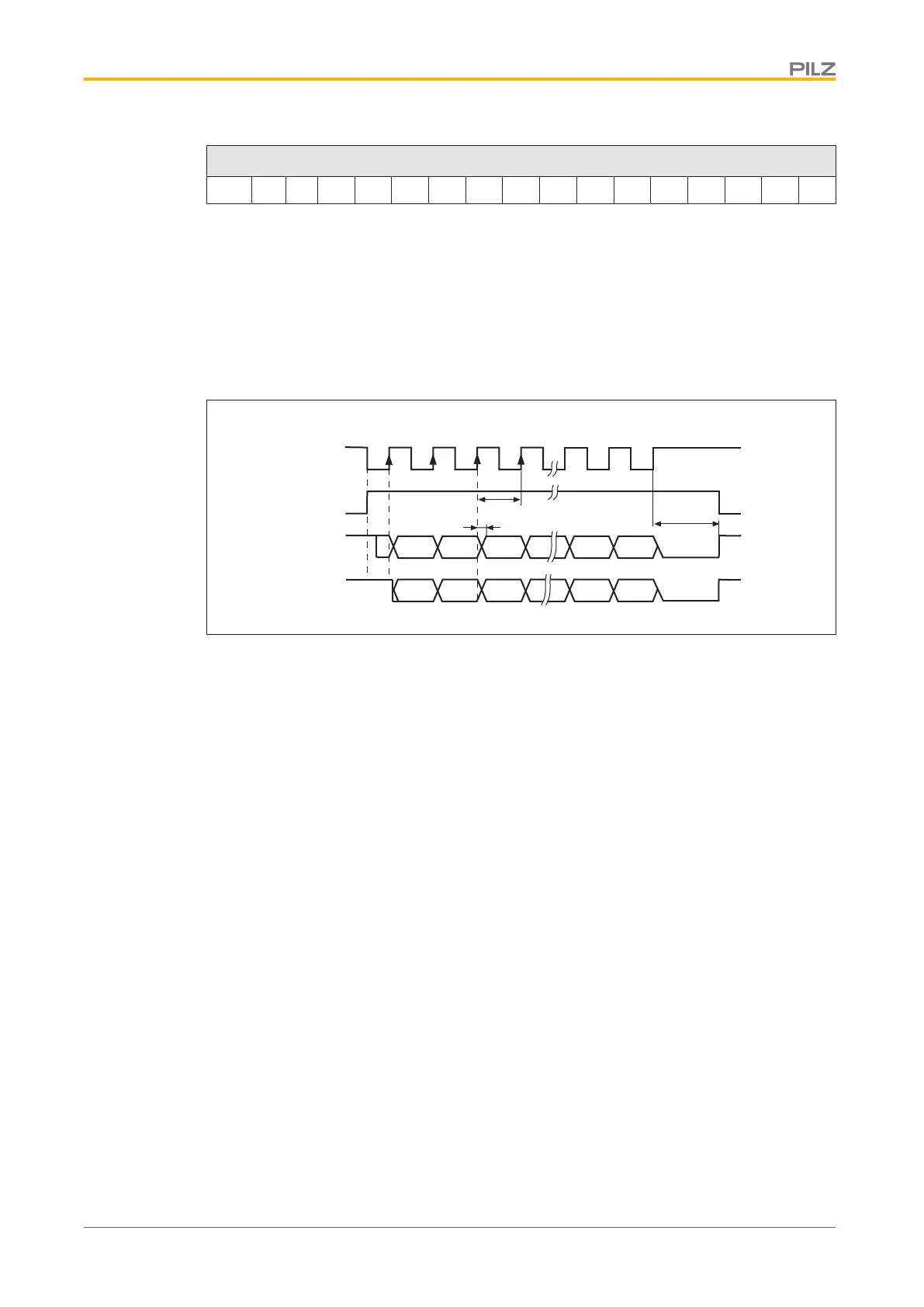
Timing diagram:
Clock
Monoflop
Gray
Binär
1 2 3
4
2
31
2
0
G31
G0
T
t
v
33
32
t
p
Fig.: Timing diagram in gray and binary code
} Switch over time for data t
v
≤ 300 ns
} Min. period length T = 600 ns
} Timeout t
p
= 1.3 μs or 10 μs (SSITOUT parameter)
} Output |ΔU|
} I ≥ 2 V/20 mA
} Input |ΔU| ≥ 0.3 V
} Default count direction: Upwards, facing the motor axis when rotating clockwise
4.3.8 Communications interfaces
4.3.8.1 RS 232 interface
The servo amplifier has an RS232 interface with minimum configuration (TxD, RxD, GND):
} Using the commissioning software, you can use the RS232 interface to set the following
parameters on a PC:
– Operating parameters
– Position control parameters
– Motion block parameters
} The interface is selected and set-up in the commissioning software.
For further information please refer to the chapter entitled "Wiring".
 Loading...