Function Description
Operating Manual PMCprotego D.48, PMCprotego D.72
1001735-EN-04
81
4.5.1 Normal mode
The behaviour of the servo amplifier always depends on the current setting of various para-
meters (e.g. ACTFAULT, VBUSMIN, VELO, STOPMODE, see commissioning software's
online help).
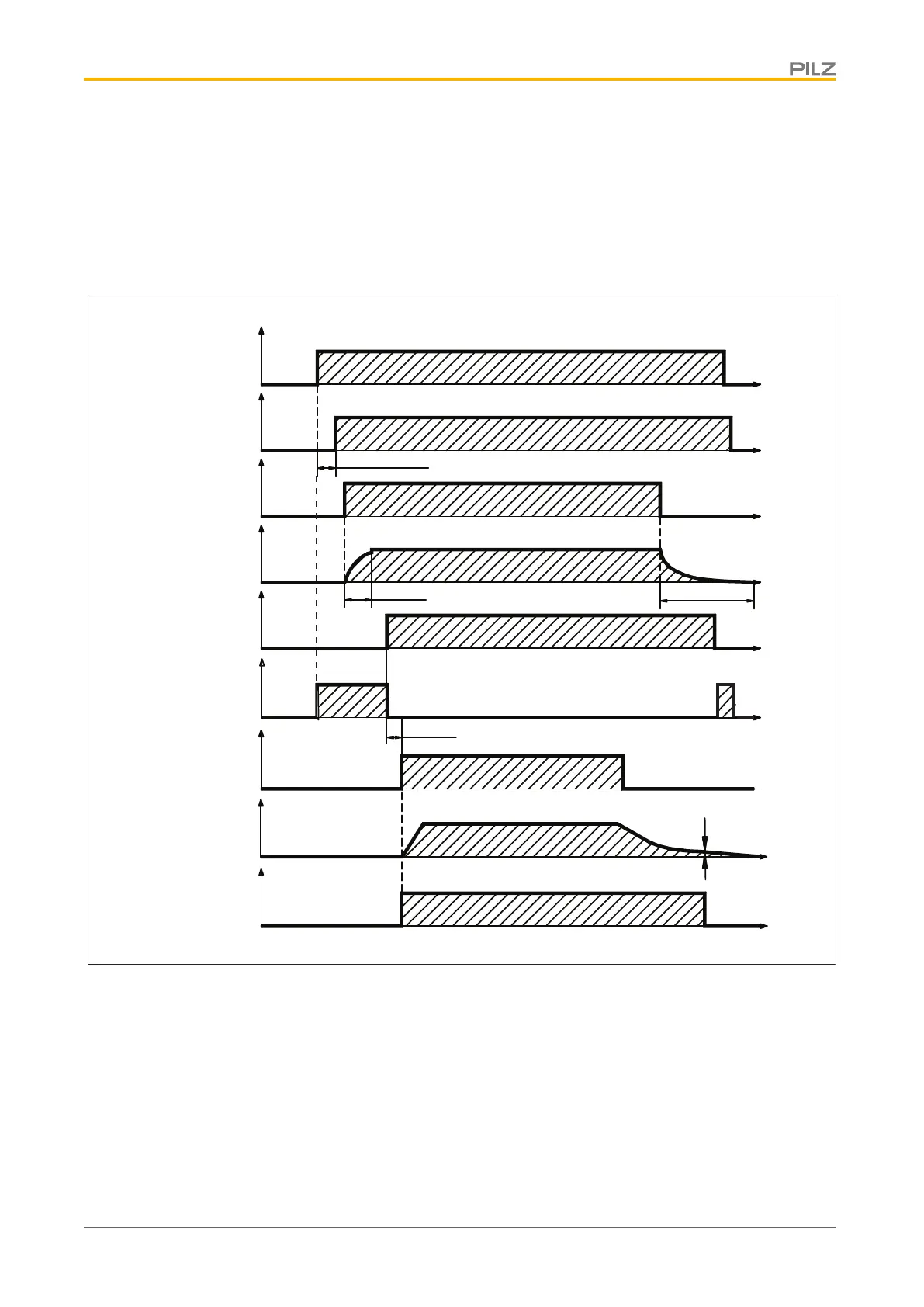
The diagram below illustrates the correct functional sequence when switching the servo
amplifier on and off.
24 V
X4/1
BTB/RTO
X3B/14,15
L1,L2,L3
X0
Intermediate
circuit X8
STO-ENABLE
X4/5, 7
HW-ENABLE
X3A/1
SW-ENABLE
Motor
speed
Output stage
enable
(internal)
<15 s (Boot-time)
~ 500 ms
VEL0
5
U
U
U
U
U
U
n
t
t
t
t
t
t
t
t
>100 ms
U
t
STO-Status
X4/6, 8
5...8 min
Fig.: Switching on and off under normal conditions
Servo amplifiers on which the “Holding brake” function has been enabled have a separate
procedure to switch off the inverted rectifier (see section in this chapter entitled “Motor hold-
ing brake”).
The drive is shut down safely using the safety function STO (STO1-ENABLE/STO2-EN-
ABLE).
 Loading...