Wiring
Operating Manual PMCprotego D.48, PMCprotego D.72
1001735-EN-04
171
6.8.3.2 Encoder emulation
Output of incremental encoder signals
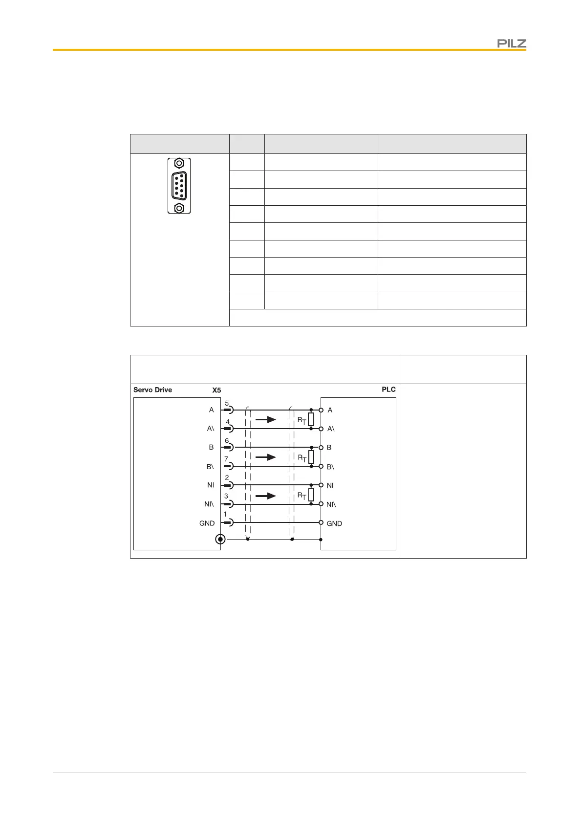
Connector X5 Pin Designation Description
1 GND Ground
2 NI Zero pulse
3 NI\ Zero impulse inverted
4 A\ Channel A inverted
5 A Channel A
6 e Channel B
7 B\ Channel B inverted
8 n.c. --
9 n.c. --
n.c.: Not connected
Connector pin assignment
Output circuit Output of incremental en-
coder signals
Shield connection in the
connector
Always connect GND to the
earth on the control system
Select R
T
in accordance
with the cable impedance,
typically 150Ω
Max. cable length: 100m
Connection
 Loading...