Wiring
Operating Manual PMCprotego D.48, PMCprotego D.72
1001735-EN-04
125
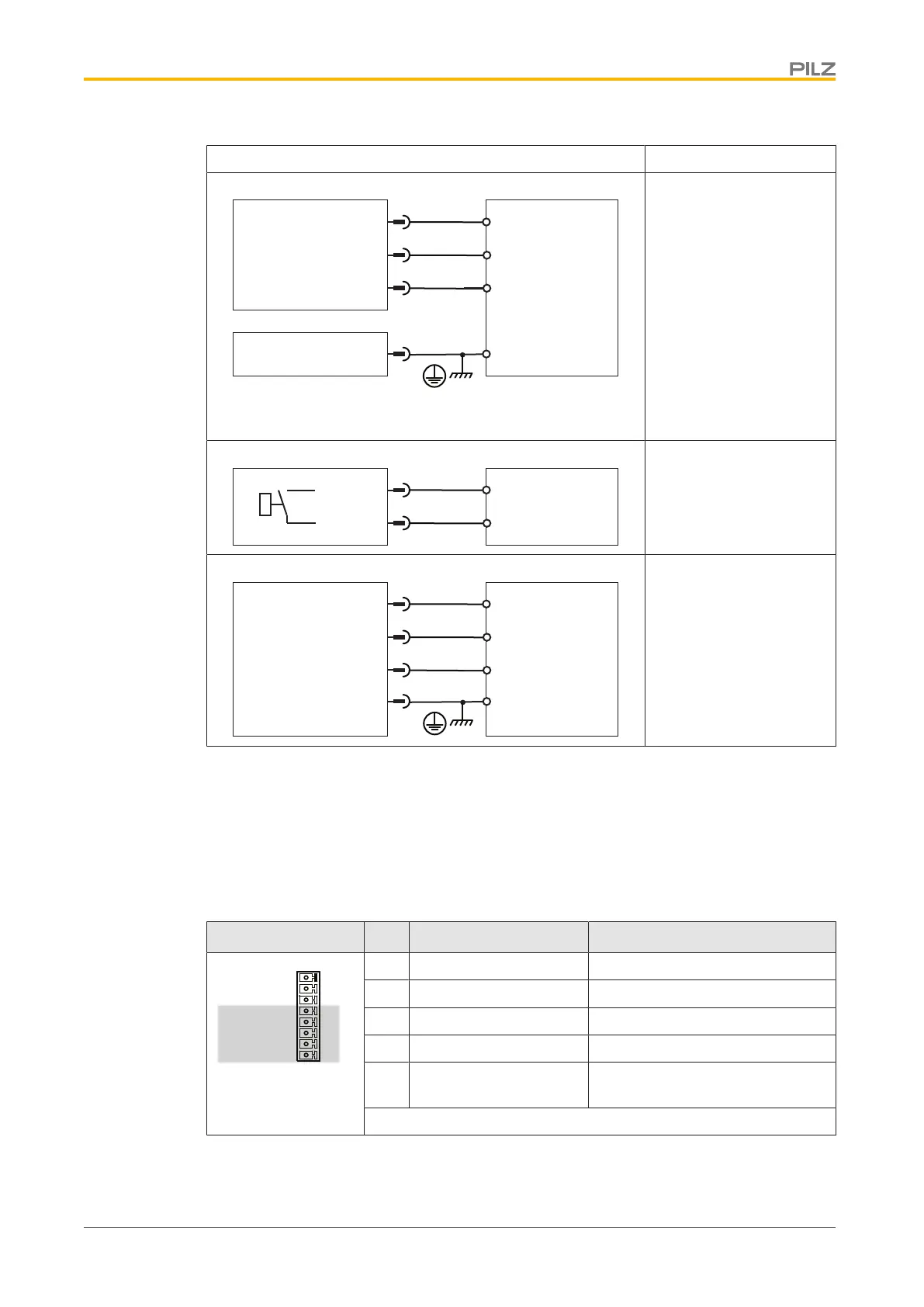
Output circuit Digital output
DI 2
6
7
8
DGND
PMCprotego
24 V
I/O-GND
X3A
DIGITAL-INOUT1
DIGITAL-INOUT2
X3B
16
DI 1
24 V
24 VDC
Referenced to earth: Al-
ways connect DGND
(X3B/16) to I/O-GND on
the control system
Pin 6 and 7 must be con-
figured as a digital output
in the commissioning soft-
ware
I 2
14
15
PMCprotego
X3B
BTB/RTO
I 1
BTB/RTO
Relay contact for opera-
tional readiness, servo
amplifier
DI 2
8
6
1
DGND
PMCprotego
24 V
I/O-GND
X4
STO1-STATUS
3
DI 1
+24 V
STO2-STATUS
24 VDC
Referenced to earth: Al-
ways connect DGND
(X4/3) to I/O-GND on the
control system
Connection
6.7.4 Analogue inputs
Under “Connection cables”, please note the requirements for the:
} Cable cross sections
} Insulation material
Connector X3B Pin Designation Description
X3B
9
10
12
13
14
15
16
11
DGND
BTB/RTO
BTB/RTO
ANALOG-IN 2+
ANALOG-IN 2-
ANALOG-IN 1+
ANALOG-IN 1-
AGND
9 ANALOG-IN1- Analogue input 1-
10 ANALOG-IN1+ Analogue input 1+
11 ANALOG-IN2- Analogue input 2-
12 ANALOG-IN2+ Analogue input 2+
13 AGND Reference earth for analogue in-
puts
Connector pin assignment
 Loading...