Wiring
Operating Manual PMCprotego D.48, PMCprotego D.72
1001735-EN-04
173
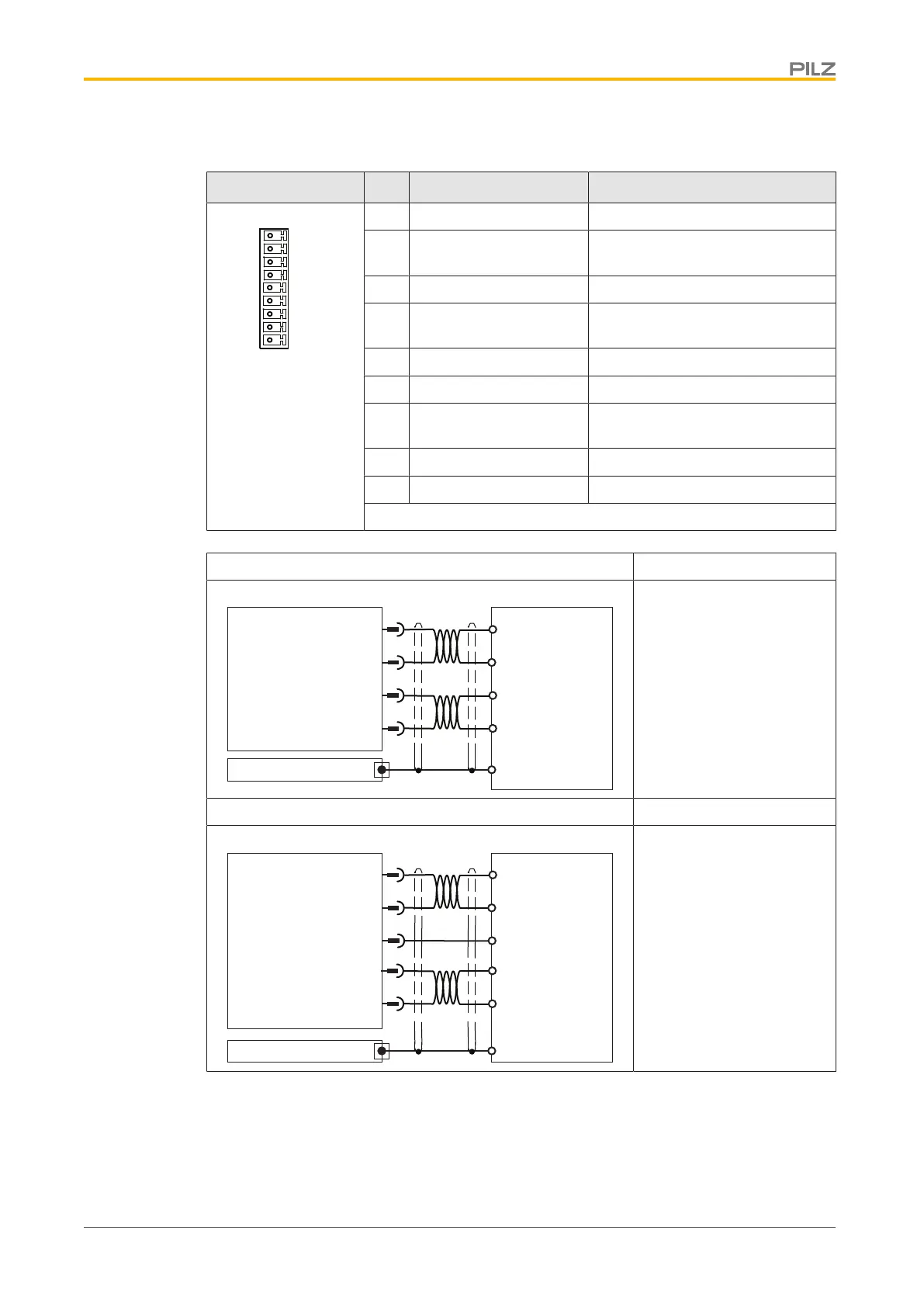
6.8.3.3 Analogue inputs and outputs
Connector X3C Pin Designation Description
17 ANALOG-OUT1 Analogue output 1
18 AGND Reference earth for analogue out-
put 1
19 ANALOG-OUT2 Analogue output 2
20 AGND Reference earth for analogue out-
put 2
21 ANALOG-IN3- Analogue input 3-
22 ANALOG-IN3+ Analogue input 3+
23 AGND Reference earth for analogue in-
puts
24 ANALOG-IN4- Analogue input 4-
24 ANALOG-IN4+ Analogue input 4+
Output circuit Analogue output
PLC-GND
17
ANALOG-OUT1
18
19
20
PMCprotego
AI 1
+/- 10 V
AI 2
PLC-GND
+/- 10 V
GND
X3C
Shield
AGND
AGND
ANALOG-OUT2
PLC
- Signal range –10 ... +10 V
- Referenced to earth: Al-
ways connect AGND
(X3B/13) to PLC-GND on
the control system
- Twisted pair, shielded
- Shield connection on the
front plate
Input circuit Analogue input
+O1
21
ANALOG-IN3-
22
23
25
AGND
PMCprotego
-O1
+/- 10 V
+O2
-O2
+/- 10 V
CNC-GND
GND
X3C
Shield
ANALOG-IN3+
ANALOG-IN4-
ANALOG-IN4+
24
- Signal range –10 ... +10 V
- Referenced to earth: Al-
ways connect AGND
(X3B/13) to CNC-GND on
the control system
- Twisted pair, shielded
- Shield connection on the
front plate
Connection
 Loading...