Wiring
Operating Manual PMCprotego D.48, PMCprotego D.72
1001735-EN-04
182
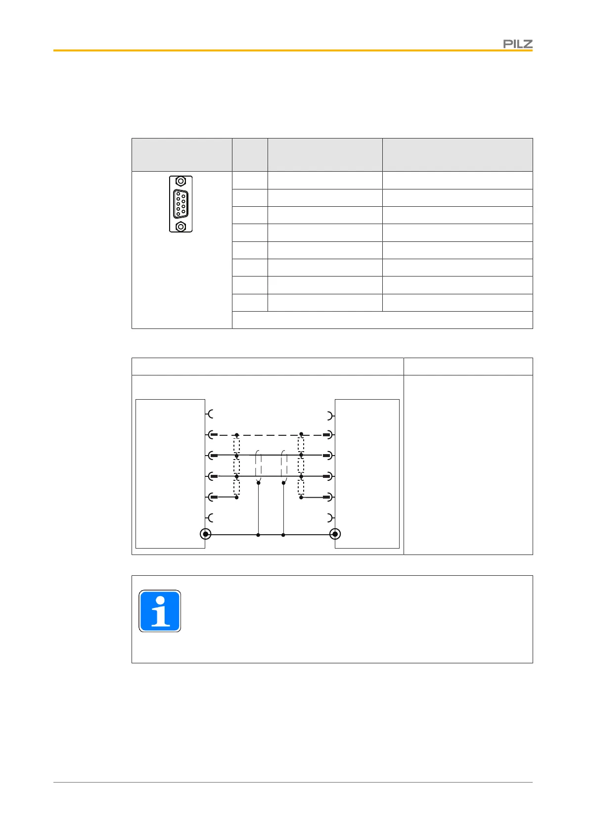
6.8.4 Expansion card with PROFIBUS-DP interface
Connector X12A/
X12B Pin Designation Description
1 n.c. --
2 n.c. --
3 RxD/TxD-P B-line
4 n.c. --
5 GND Ground
6 VP Supply voltage +5 V DC
7 n.c. --
8 RxD/TxD-N A-line
n.c.: Not connected
Connector pin assignment
Interface PROFIBUS DP
1
4
6
Servo Drive
PLC
3
A (RxD/TxD-N)
GND
VP
390 W
390 W
390 W
220 W
220 W
390 W
5
8
1
4
6
3
5
8
B (RxD/TxD-P)
A (RxD/TxD-N)
GND
VP
B (RxD/TxD-P)
X12A
X12B
Shielded cable
Shield connection in the
connector
Connection
INFORMATION
Cable selection, cable routing, shielding, bus connectors, bus termination
and runtimes are all described in the “PROFIBUS-DP/FMS Installation
Guidelines” published by the PROFIBUS User Group PNO.
 Loading...