Wiring
Operating Manual PMCprotego D.48, PMCprotego D.72
1001735-EN-04
167
6.8.2 Expansion card I/O-14/08
Under “Connection cables”, please note the requirements for the:
} Cable cross sections
} Insulation material
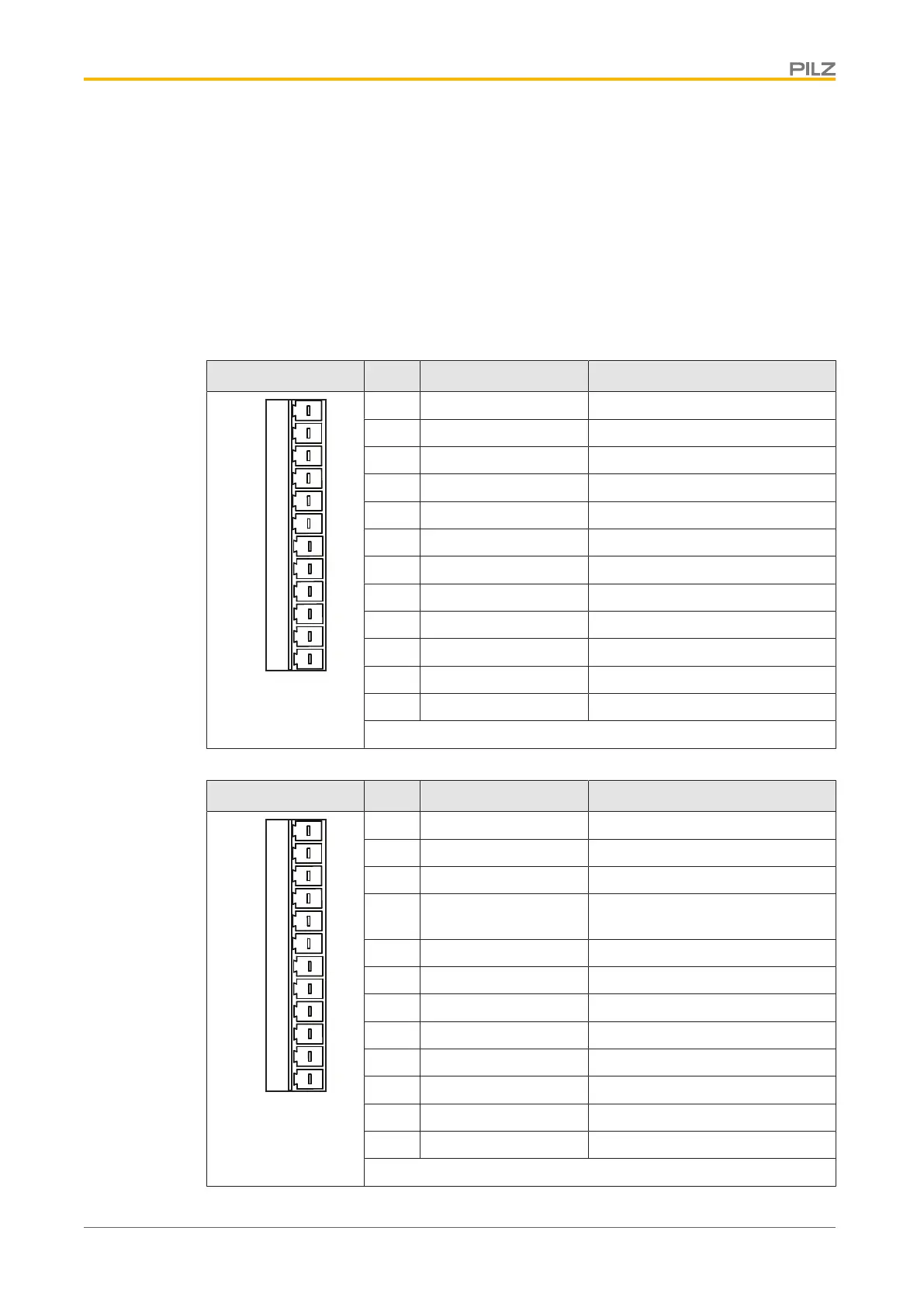
The assignment of the inputs and outputs in the tables below is the default setting (“Con-
nector pin assignment” table, under “Designation”). It can be changed at any time in the
commissioning software (see chapter entitled “Function Description” for details of the ex-
pansion card).
Connector X11A Pin Designation Description
3 4 5 61 2 7 8 9 10 11 12
X11A
1 A0 Digital input
2 A1 Digital input
3 A2 Digital input
4 A3 Digital input
5 A4 Digital input
6 A5 Digital input
7 A6 Digital input
8 A7 Digital input
9 Reference Digital input
10 S_fehl_clear Digital input
11 FStart_Folge Digital input
12 FStart_Tipp x Digital input
Connector pin assignment
Connector X11B Pin Designation Description
3 4 5 61 2 7 8 9 10 11 12
X11B
1 FRestart Digital input
2 FStart_I/O Digital input
3 InPosition Digital output
4 Folge-InPos / PosReg
0
Digital output
5 S_fehl Digital output
6 PosReg1 Digital output
7 PosReg2 Digital output
8 PosReg3 Digital output
9 PosReg4 Digital output
10 PosReg5 Digital output
11 24 VDC Supply voltage 24 VDC
12 I/O-GND Reference earth
 Loading...