Wiring
Operating Manual PMCprotego D.48, PMCprotego D.72
1001735-EN-04
124
6.7.3 Digital outputs
Under “Connection cables”, please note the requirements for the:
} Cable cross sections
} Insulation material
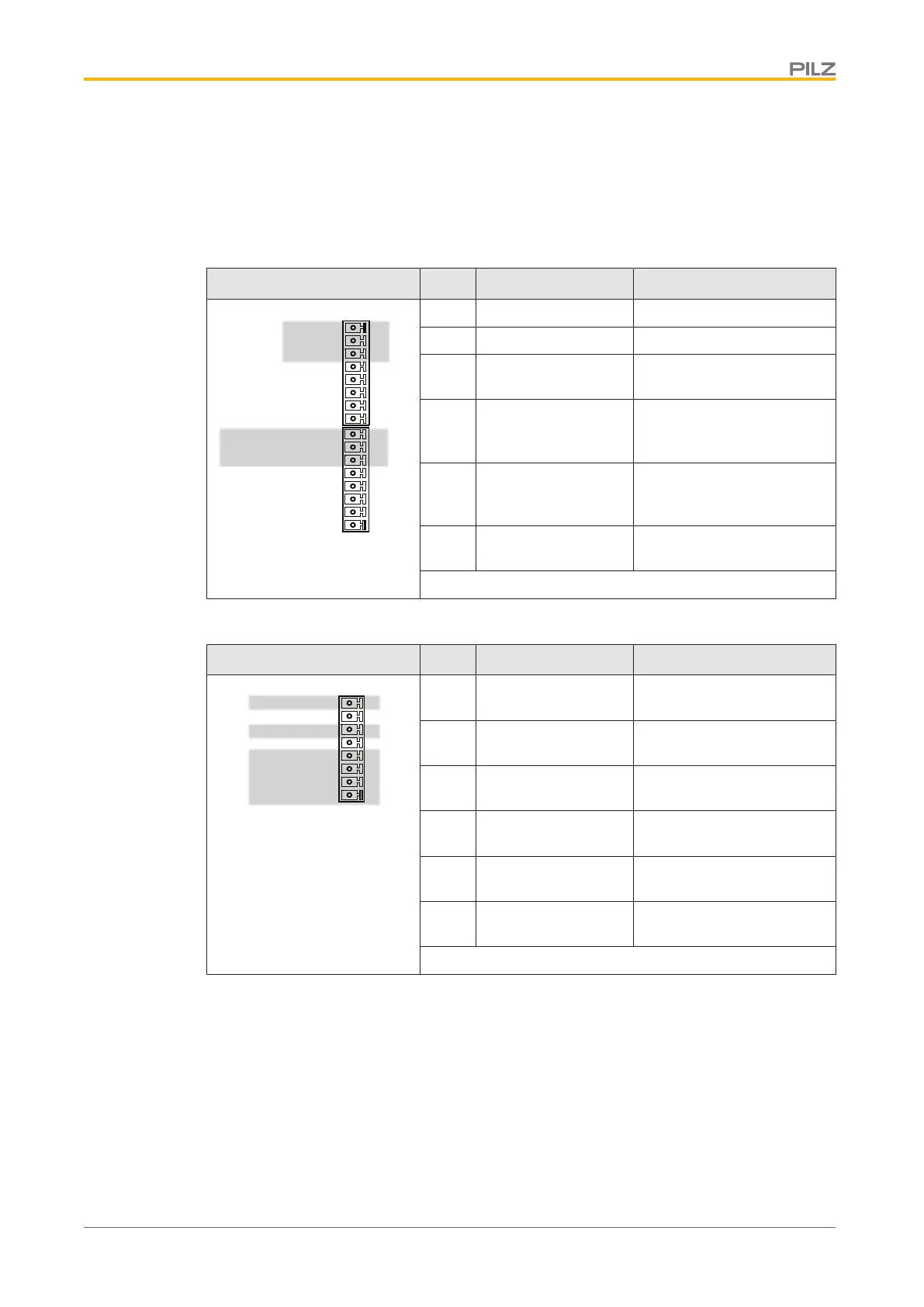
Connector X3A/X3B Pin Designation Description
X3B
1
2
3
4
X3A
5
6
7
8
9
10
12
13
14
15
16
11
DGND
BTB/RTO
BTB/RTO
ANALOG-IN 2+
ANALOG-IN 2-
ANALOG-IN 1+
ANALOG-IN 1-
AGND
+24V-IO
DIGITAL-IN22/OUT2
DIGITAL-IN21/OUT1
DIGITAL-IN4
DIGITAL-IN3
DIGITAL-IN2
DIGITAL-IN1
ENABLE
6 DIGITAL-INOUT 1 Digital input or output 1
7 DIGITAL-INOUT 2 Digital input or output 2
8 24 V Supply voltage for digital
outputs
14 BTB/RTO Relay contact for opera-
tional readiness, servo
amplifier
15 BTB/RTO Relay contact for opera-
tional readiness, servo
amplifier
16 DGND Reference earth for digital
inputs or outputs
Connector pin assignment
Connector X4 Pin Designation Description
X4
XGND
STO1-STATUS
1
2
3
4
5
6
7
8
STO2-STATUS
STO1-ENABLE
STO2-ENABLE
XGND
+24V
+24V
1 +24 V Supply voltage for digital
outputs
2 +24 V Supply voltage for digital
outputs
3 XGND Reference earth for digital
inputs or outputs
4 XGND Reference earth for digital
inputs or outputs
6 STO2-STATUS Status of safety function
STO
8 STO1-STATUS Status of safety function
STO
Connector pin assignment
 Loading...