Function Description
Operating Manual PMCprotego D.48, PMCprotego D.72
1001735-EN-04
48
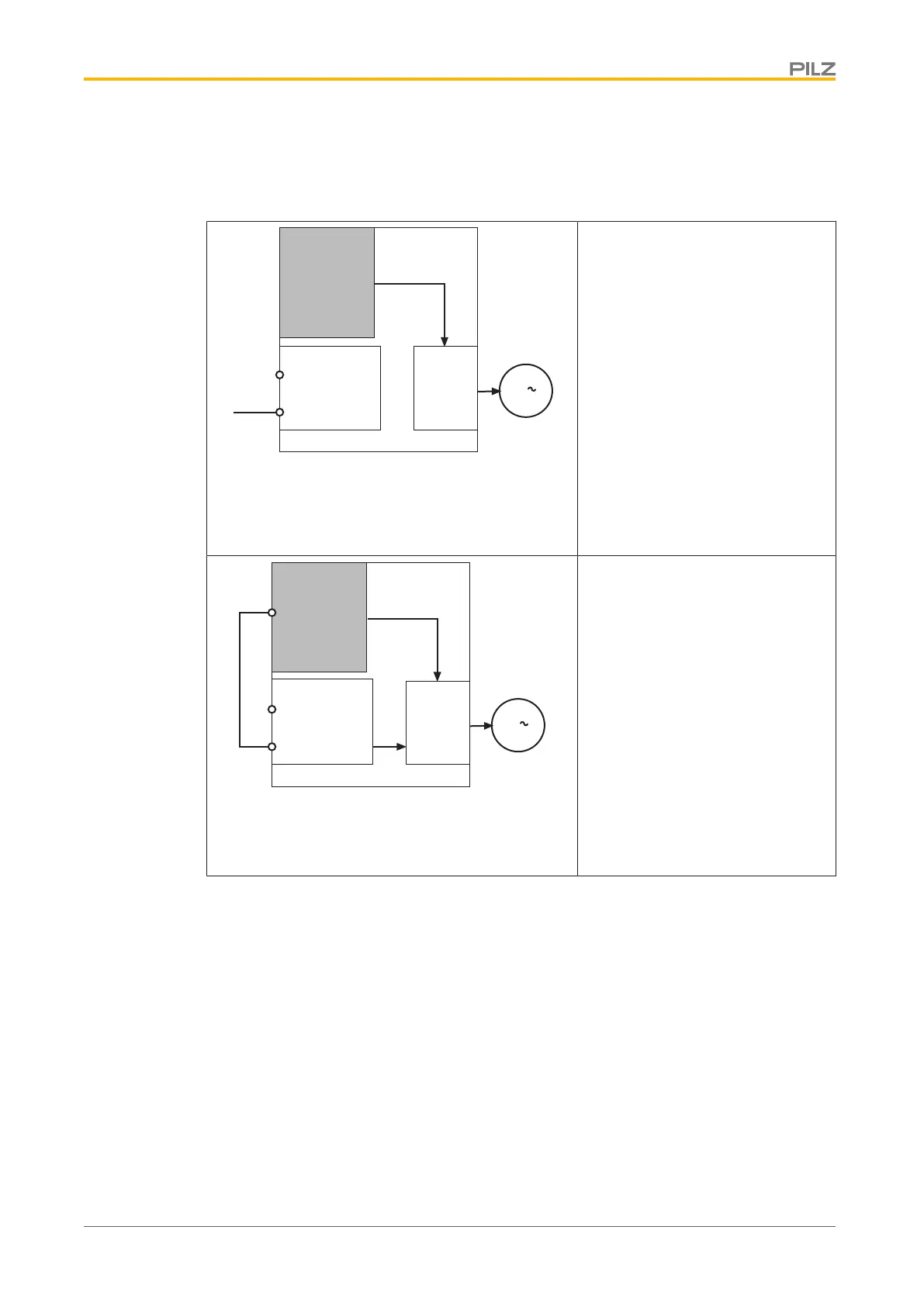
4.3.3.4 Safety function STO with safety card
With a safety card inserted, activation of the safety function STO can be single or dual-
channel.
X4
STO1-ENABLE
STO2-ENABLE
7
5
PMCprotego D.x
PMCprotego S2
24 V
POWER
3
STO
STO single-channel with safety card
PMCprotegoS2 (or when the 2nd
shutdown route is not used on the
safety card PMCprotegoS1)
Safety function is activated intern-
ally via the safety card's STO func-
tion.
The input STO1-ENABLE has no
function.
The input STO2-ENABLE must be
connected to 24VDC.
X4
STO1-ENABLE
STO2-ENABLE
7
5
PMCprotego D.x
PMCprotego S1
X30
19
STO SIL3
STO
STO
POWER
3
STO dual-channel with safety card
PMCprotegoS1
Safety function is activated intern-
ally via the safety card's STO func-
tion
and
output STO SIL3 on the safety card
is connected to STO2-ENABLE as
a 2nd shutdown route.
The input STO1-ENABLE has no
function.
4.3.3.5 Reaction time
The reaction time of the safety function STO, from the falling edge at the inputs STO1-EN-
ABLE and STO2-ENABLE to the removal of power to the motor, is
} 5 ms on the shutdown route STO1
} 5 ms on the shutdown route STO2
4.3.3.6 Connection example for STO, single-channel
The following circuit example illustrates single-channel activation of the safety function
STO.
} The drives are switched via a safety gate.
} Safety gates S1/S2 are monitored by a safety relay PNOZs3.
} Shorts across contacts are detected.
 Loading...