Wiring
Operating Manual PMCprotego D.48, PMCprotego D.72
1001735-EN-04
170
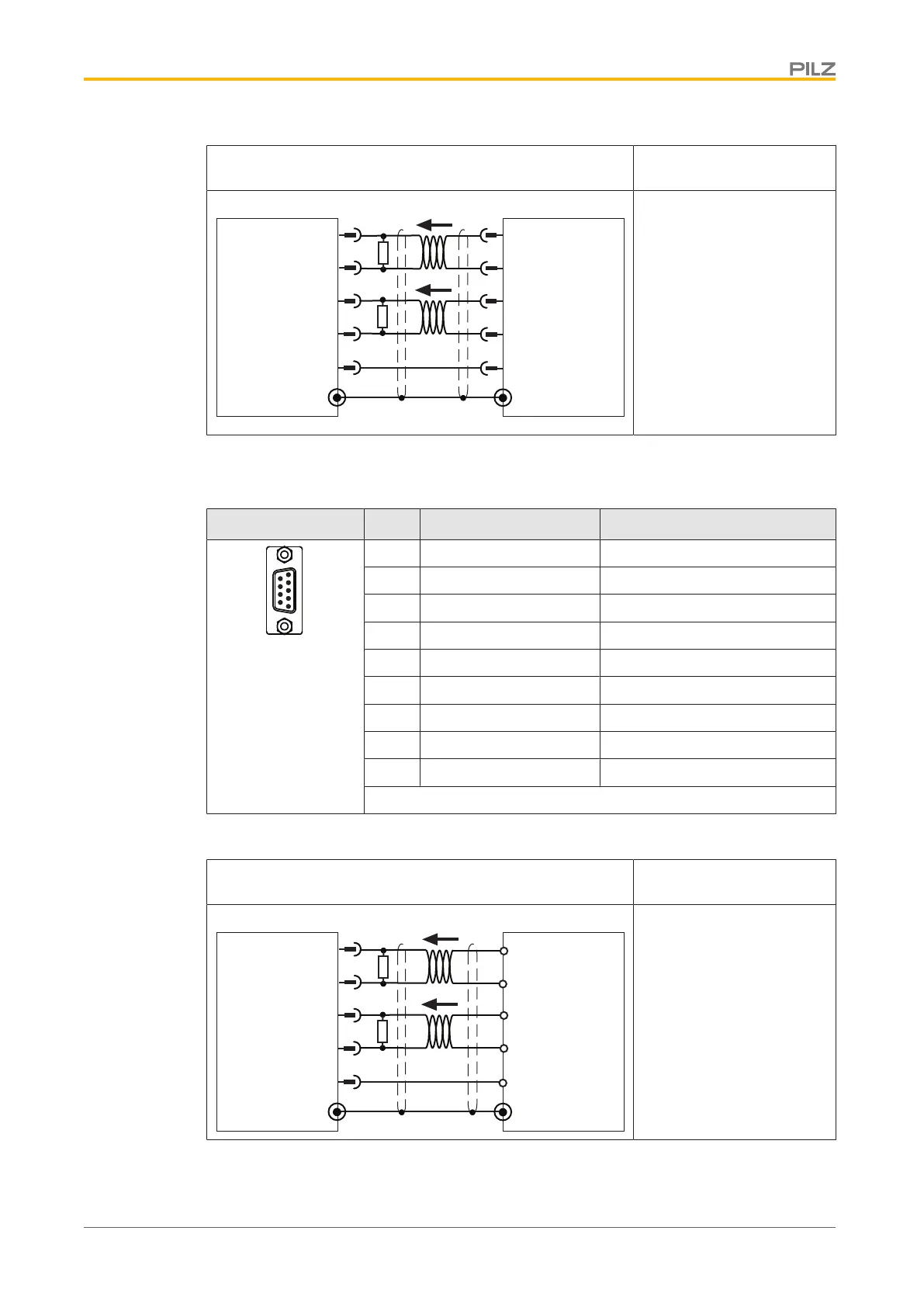
Output circuit Output of incremental en-
coder signals
6
7
4
Servo Drive Slave
X5
5
B+
B-
A+
A-
GND
1
R
T
Servo Drive Master
R
T
X5
B+
B-
A+
A-
GND
6
7
4
5
1
Always connect GND to the
earth on the control system
Twisted pair, shielded
Select R
T
in accordance
with the cable impedance,
typically 150Ω
Connection
Connection to a stepper motor control system with 5V signal
Connector X5 Pin Designation Description
1 GND Ground
2 n.c. --
3 n.c. --
4 P- Pulse inverted
5 P+ Pulse
6 D+ Direction
7 D- Direction inverted
8 n.c. --
9 n.c. --
n.c.: Not connected
Connector pin assignment
Output circuit Output of incremental en-
coder signals
6
7
4
Servo Drive
X5
5
1
R
T
Master
R
T
D+
D-
P+
P-
GND
D+
D-
P+
P-
GND
Always connect GND to the
earth on the control system
Twisted pair, shielded
Select R
T
in accordance
with the cable impedance,
typically 150Ω
Connection
 Loading...