Function Description
Operating Manual PMCprotego D.48, PMCprotego D.72
1001735-EN-04
66
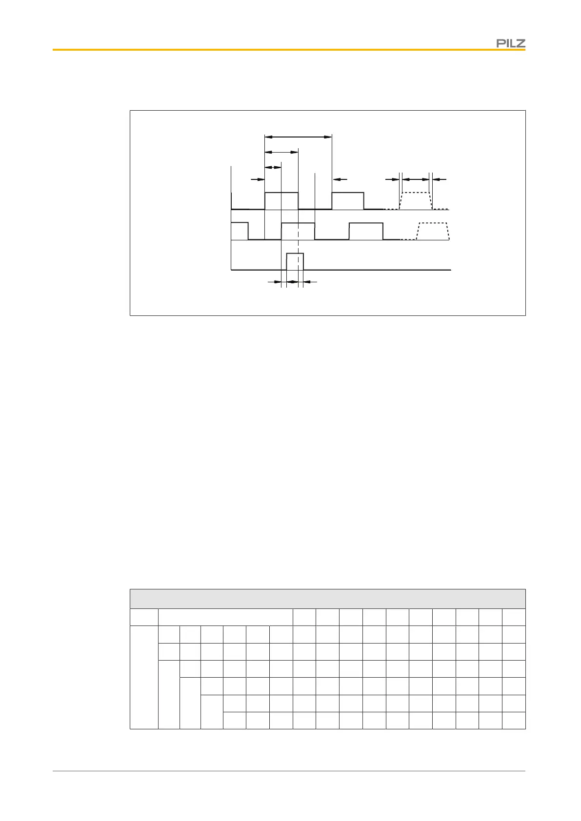
Timing diagram for the incremental encoder signal:
A
B
NI
5 V
5 V
5 V
aa a a
tvtv
tdtd
90°
180°
360°
} a: Edge spacing ≥ 0.2 μs
} tv: Edge steepness ≤ 0.1 μs
} NI – td: Delay ≤ 0.1 μs
} |ΔU| ≥ 2 V/20 mA
} Default count direction: Upwards, facing the motor axis when rotating clockwise
Output of SSI signals
Functions:
With this encoder emulation, positional data for the SSI interface is prepared from the exist-
ing output signals from the resolver or SinCos encoder.
} A max. 32Bits are transferred.
} Singleturn: The leading 12 to 16Bits are zero, the following 16Bits indicate the posi-
tion. On 2-pole resolvers the position value refers to a full revolution of the motor; on 4-
pole resolvers it refers to half a revolution and on 6-pole resolvers to one third of a re-
volution.
} Multiturn: The leading 12 to 16Bits indicate the number of revolutions; the following 16
bits state the position.
Revolution
SSIREVOL
Bit
15 14 13 12 11 10 9 8 7 6 5 4 3 2 1 0
14 13 12 11 10 9 8 7 6 5 4 3 2 1 0
13 12 11 10 9 8 7 6 5 4 3 2 1 0
12 11 10 9 8 7 6 5 4 3 2 1 0
11 10 9 8 7 6 5 4 3 2 1 0
 Loading...