Wiring
Operating Manual PMCprotego D.48, PMCprotego D.72
1001735-EN-04
121
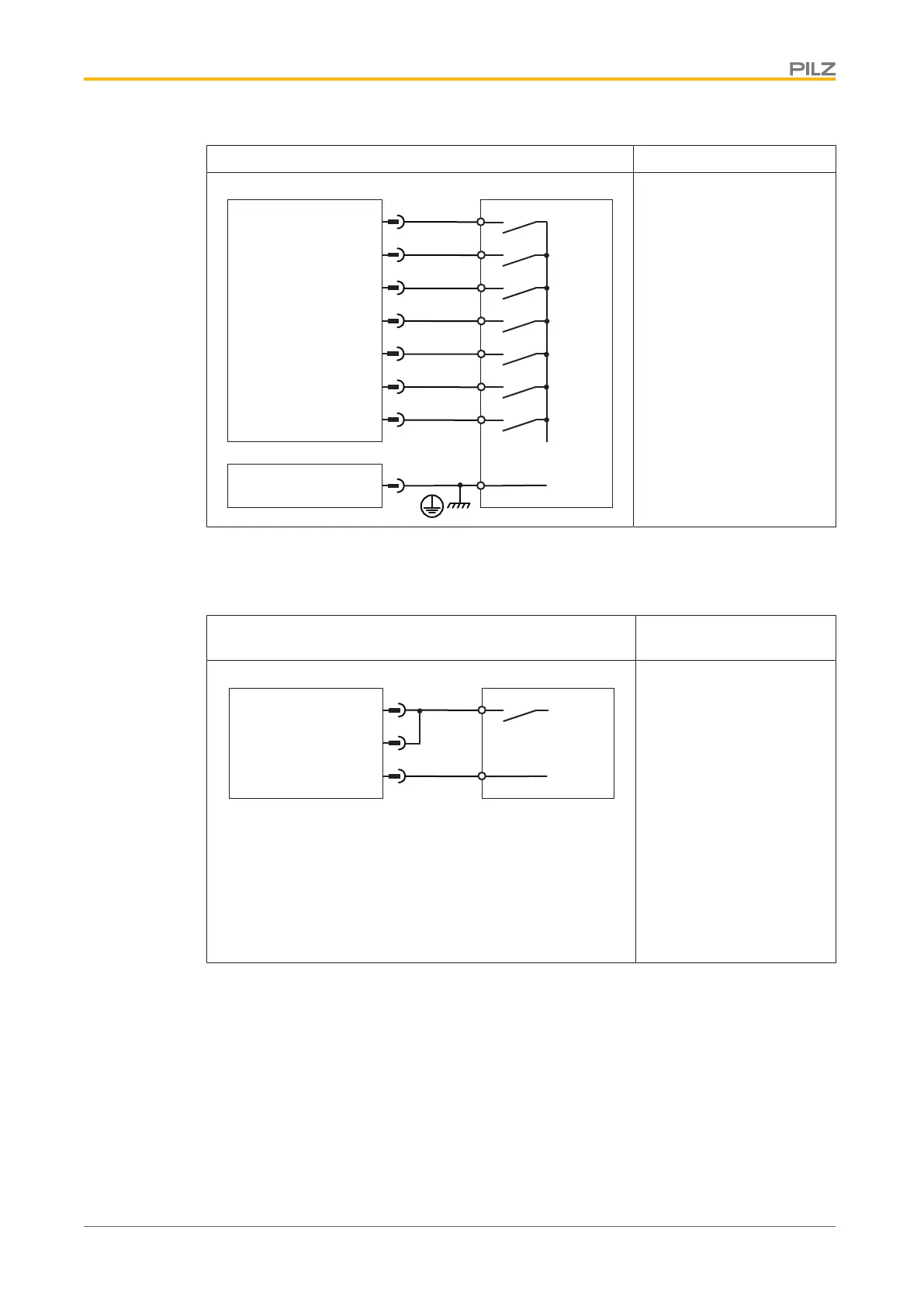
Input circuit Digital input
NSTOP
1
ENABLE
DIGITAL-IN1
2
3
4
DGND
5
PMCprotego
24 V
I/O-GND
X3A
DIGITAL-INOUT1
DIGITAL-IN4
DIGITAL-IN3
DIGITAL-IN2
DIGITAL-INOUT2
6
7
X3B
16
ENABLE
PSTOP
24 VDC
Referenced to earth: Al-
ways connect DGND
(X3B/16) to I/O-GND on the
control system
PSTOP, NSTOP: Evalu-
ation of limit switch
Pin 6 and 7 is configured as
a digital input in the com-
missioning software
Connection
PMCprotego D without a safety card
Input circuit Digital input: STO1-EN-
ABLE/STO2-ENABLE
5
IO-GND
XGND
7
PMCprotego D
X4
STO1-ENABLE
4
STO2-ENABLE
24 V
Single-channel
24 VDC
Referenced to earth: Al-
ways connect XGND
(X4B/3 or 4) to I/O-GND on
the control system
Connect a safe semicon-
ductor output or positive-
guided relay contact
 Loading...