Wiring
Operating Manual PMCprotego D.48, PMCprotego D.72
1001735-EN-04
175
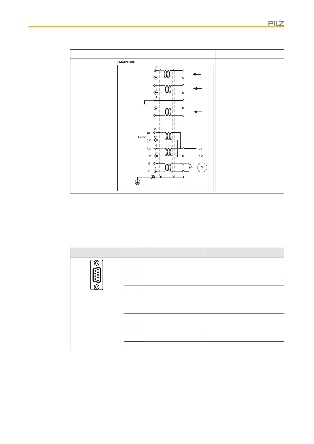
Input circuit Incremental encoder 5 V
X5
X1
A+
A+
A-A-
NI+
NI+
NI-
NI-
4
2
6
7
GND
GND
B+
B+
B-B-
ROD (AquadB)
Voltage supply and thermal
switch in the motor is con-
nected to X1 via the en-
coder cable.
Twisted pair, shielded
Shield connection in the
connector
Connection
Incremental encoder ROD (AquadB) 5V, with Hall
If the cable length is >25m, please speak to our Customer Support.
Connector X5 Pin Designation Description
1 GND Ground
2 NI+ Zero pulse +
3 NI- Zero pulse -
4 A- Track A-
5 A+ Track A+
6 B+ Track B+
7 B- Track B-
8 n.c. --
9 n.c. --
n.c.: Not connected
Connector pin assignment
 Loading...