Chapter 1-First Time Installation and Configuration
Polycom, Inc. 1-19
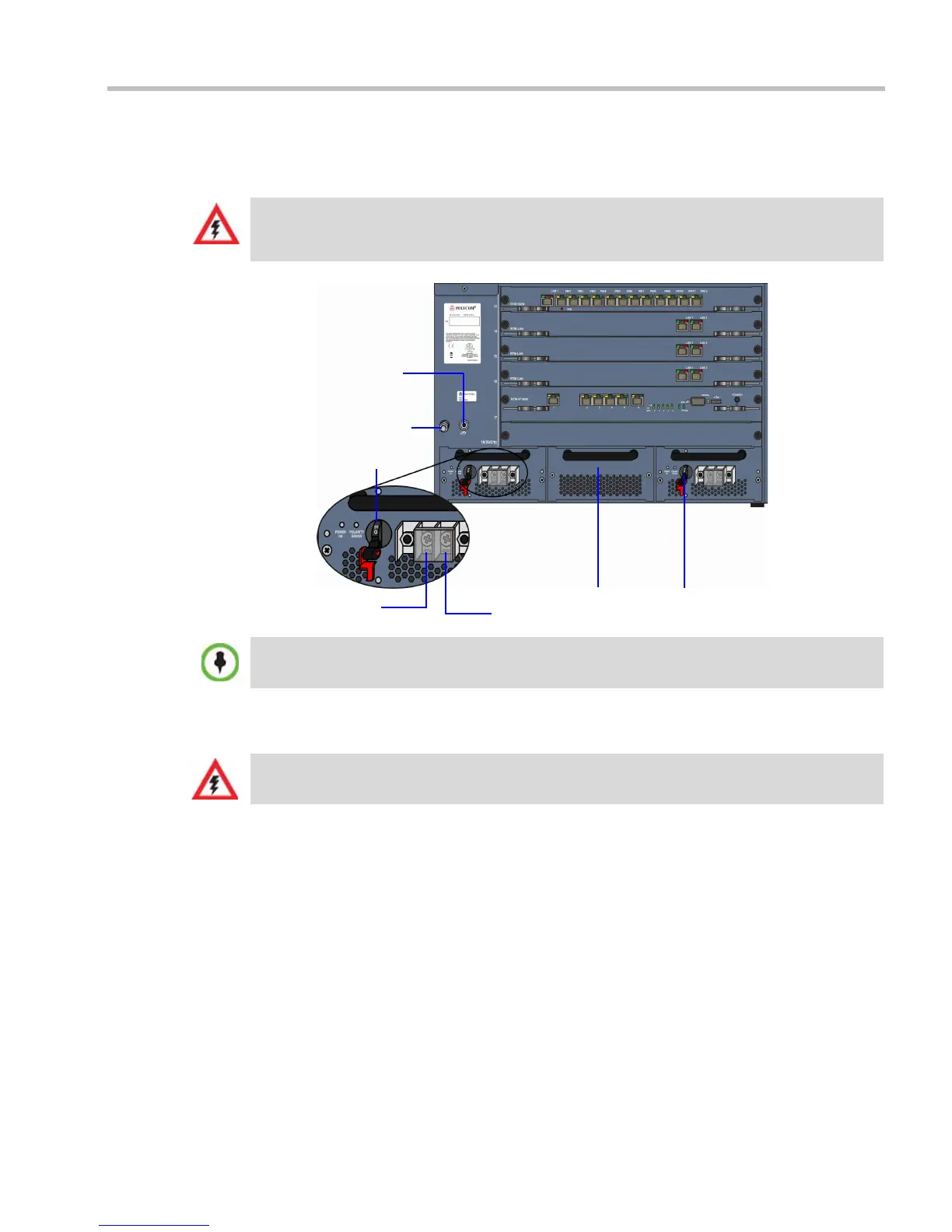
4 Using the two wires of a 10 AWG cable running from the DC power distribution unit,
connect the black wire into the -48VDC terminal block and the red wire to the RTN
terminal block.
5 Connect the green or green-yellow wire to the system single-point M6x15 “Ground”
bolt.
If the unit is rack mounted, the single-point ground on the MCU must be connected to
the rack with a single conductor and fixed as to prevent loosening. When using bare
conductors, they must be coated with an appropriate antioxidant compound before
crimp connections are made. Tinned, solder-plated or silver plated connectors do not
have to be prepared in this manner.
6 Replace the transparent plastic caps on the terminal block.
7 Turn ON the Main that supplies power to the RMX.
8 Turn ON the circuit breaker on each of the DC Power Rail Modules.
• A 10 AWG cable must be used to connect the mains with the RMX 4000 DC Power Rail Model.
• The supply wires for DC version must be terminated using quick connectors.
• Extension cords may not be used.
ESD connector
Circuit breaker - ON
position
-48 VDC
RTN
Ground connector
Blank panel
Circuit breaker - OFF
position
The center PRM slot/module is fitted with a blank panel and the slot cannot be used on a system
with DC Voltage.
The rating of the protective earthing conductor should be a minimum of 10AWG.