236
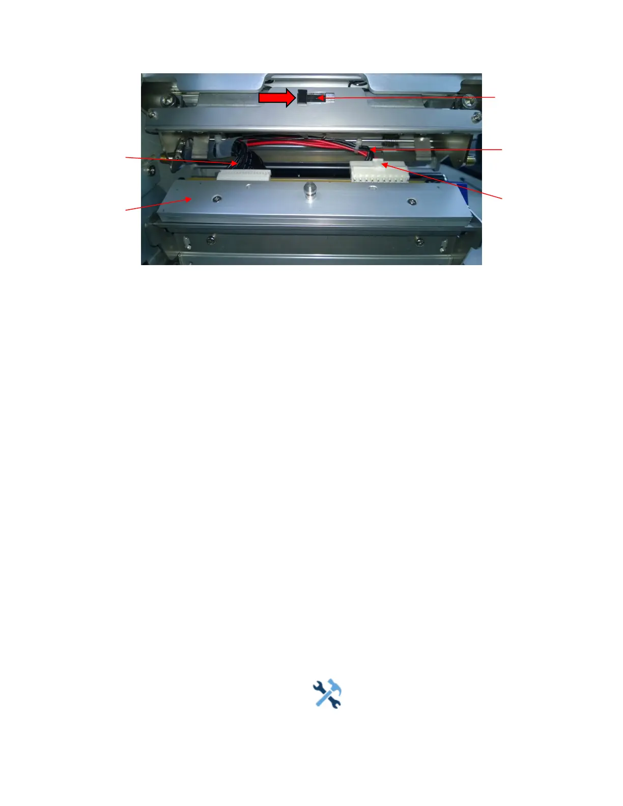
Figure 20 Replacing the Printhead Assembly
CAUTION To prevent electrostatic damage to electronic components, ground
yourself by
touching an unpainted part of the printer frame before
handling and installing
the printhead.
5.
Touch an unpainted part of the printer frame before touching the
printhead.
6.
Push the printhead assembly release tab
to right side to release the printhead assembly.
7.
Push the release tab down on the power supply cable assembly and
remove the cable from the
printhead assembly.
8.
Use the pull-tab to remove the printhead controller cable assembly from
the printhead assembly.
9.
Position the new printhead assembly below the pivoting deck and connect
the printhead controller
and power supply cable
assemblies.
10.
Slide the printhead assembly upward into the pivoting deck until the
retainer clips snap it in place.
Make sure that the cable assemblies do not
into the media or ribbon path.
Restore the Printer to Operation
1.
Inspect the light brown area of the printhead for smudges or fingerprints.
If necessary, gently
clean the light brown area with a soft, lint-free cloth
(or a cotton swab) moistened with isopropyl
alcohol, or use a Cleaning
Pen (P/N 203502-001).
2.
Install the ribbon and media (e.g., paper, label, or tag stock material).
3.
Close the pivoting deck and rotate the deck lock lever fully
counterclockwise.
(Figure 19.)
4.
Close the media cover.
5.
Plug the AC power cord into the printer and the power source.
6.
Verify the Printhead statistics from the ONLINE menu screen (the Printhead Gauge should show
100%).
7.
Test printer operation and check print quality by selecting the
Tools > Print Tests section and
printing one of the test patterns.
(Refer to Tools
on page 201).