Remote control basics
R&S
®
NRPxxS(N)
163User Manual 1177.5079.02 ─ 15
0
1
2
3
4
5
6
7
8
9
10
11
12
13
14
15
Calibrating
0
0
0
Measuring
Triggering
0
0
0
0
Sense summary
Lower limit fail
Upper limit fail
0
0
0
+
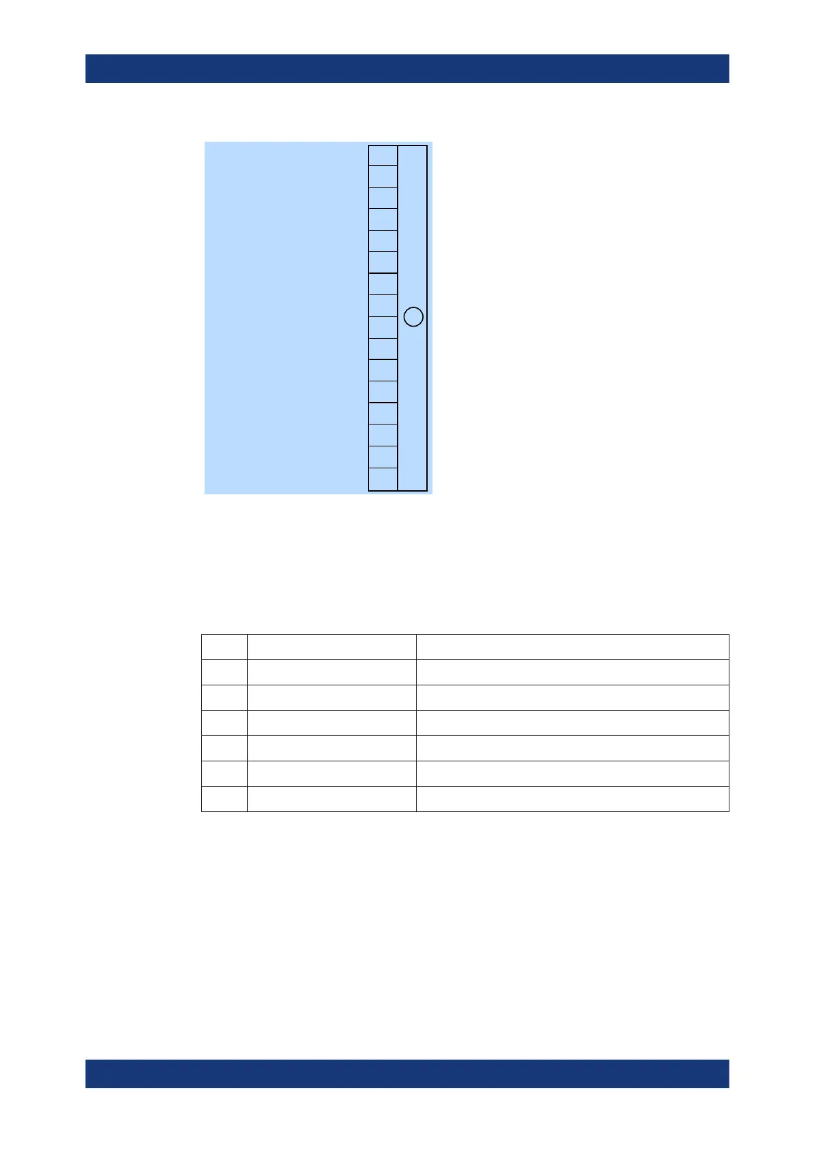
Figure 11-7: Operation status register
Querying the register:
●
STATus:OPERation:CONDition?
●
STATus:OPERation[:EVENt]?
Table 11-9: Used operation status bits and their meaning
Bit no. Short description Bit is set if
0 Calibrating Summary of Operation calibrating status register exists.
4 Measuring Summary of Operation measuring status register exists.
5 Triggering Summary of Operation trigger status register exists.
10 Sense summary Summary of Operation sense status register exists.
11 Lower limit fail Summary of Operation lower limit fail status register exists.
12 Upper limit fail Summary of Operation upper limit fail status register exists.
11.2.5.1 Operation calibrating status register
The CONDition register contains information whether a power sensor is being calibra-
ted. The EVENt register contains information whether a calibration was started or com-
pleted since the last query.
Status reporting system

 Loading...

