Order No.
35 MHz: F 8042
40 MHz: F 8043
41 MHz: F 8044
FX-30
To operate a flight simulator program using the FX-30 trans-
mitter you will need to use the adaptor lead, No. 8239, which
is available as an optional accessory.
In this case the transmitter must always be set to 8-channel
operation and FM modulation (see Base menu, Set-up menu
“Frequency”), Section 12.4.
Switching on the Trainer function when set to PPM 8 modula-
tion automatically switches the RF module off; the same
a
pplies with a 2.4 GHz system.
4.9 INPUT ELEMENTS
The FX-30 is programmed using the ‘3-D hot-key’ with EDIT
function and the S1 button, in conjunction with the large, cle-
arly arranged LCD screen.
LCD MONITOR CONTROL AREA
T
he large, clearly arranged, high-contrast LCD graphic moni-
tor, with a resolution of 255 x 96 dots, provides the user with
all the essential information during the programming procedu-
re and when using the system to control a model.
3-D HOT-KEY / EDIT BUTTON
During the programming procedure data is entered primarily
using the ‘3-D hot-key’: rotating it increases or decreases a
marked value, while - pressing it confirms the newly set values
(EDIT function).
S1 input button
The S1 button can be used to leaf through in either direction
within the individual sub-menus even when you are not direct-
ly at the special settings level. A brief press on the button
takes the cursor straight back to the starting point. To return to
the home display you must hold the button pressed in for at
least one second. The S1 button also acts as a Key Lock, to
ensure that settings are not changed accidentally while you
are flying a model. To lock and unlock the buttons first return
to the Home display, then hold the S1 button pressed in for at
least one second.
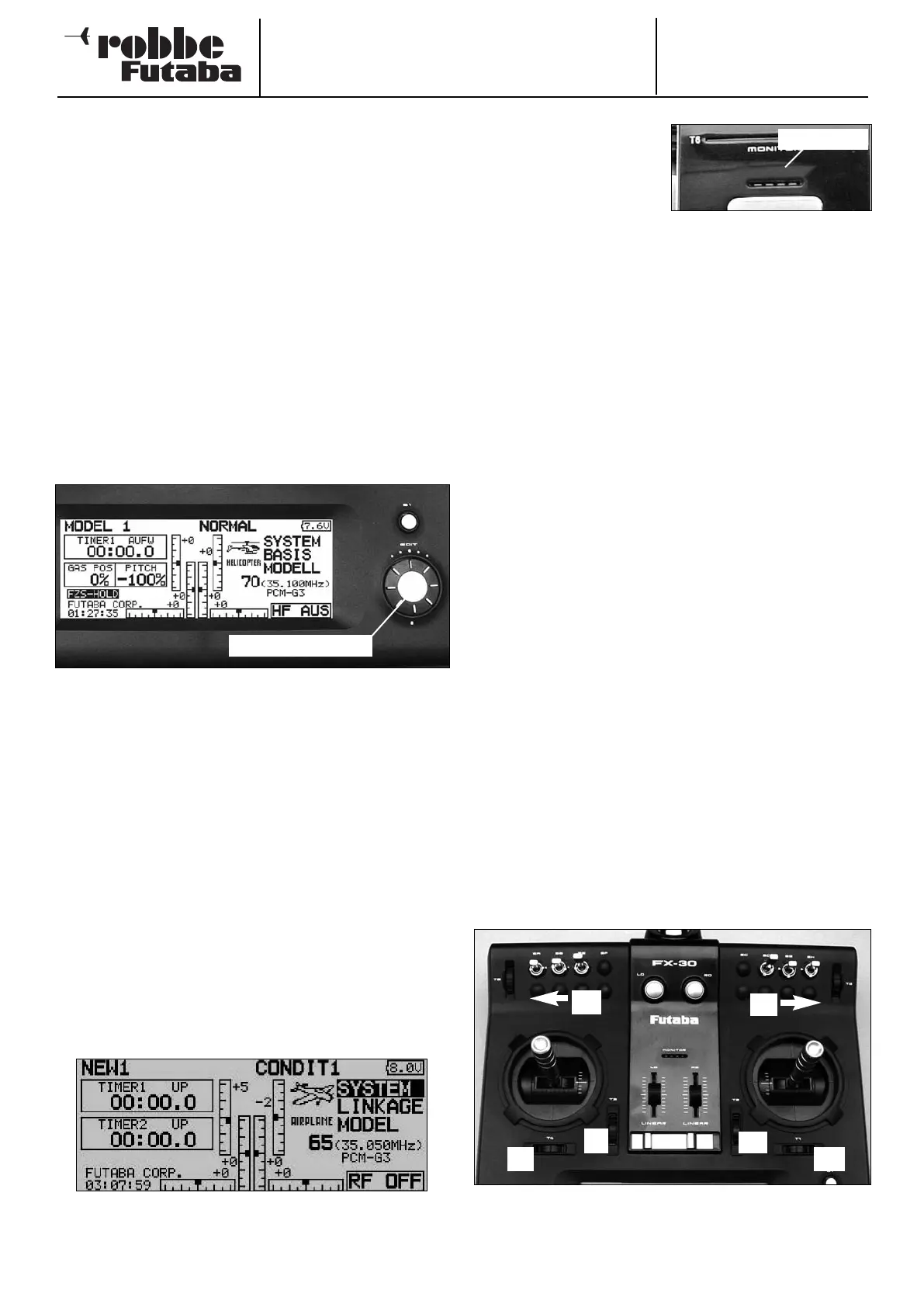
The screen-shot shows the Start screen. See Section 9 for a
description of the individual displays.
4.10 LED STATUS
On the front panel you will
find two status LEDs which
indicate the transmitter sta-
tus by means of flashing
sequences and colours.
• When you switch the transmitter on, the red LED lights up.
•
A green LED flashing slowly indicates that the spot fre-
quency is being transmitted to the receiver.
• The LED monitor colour changes to green when the DSC
lead is connected, and when the transmitter is active as a
Pupil transmitter for Trainer mode operations.
• If the LED monitor flashes red slowly, this indicates that no
RF module is present, or that the RF module in the trans-
mitter does not match the transmitter or the selected fre-
quency band.
SUMMARY OF THE MOST IMPORTANT COLOUR INDICA-
TORS:
LED glows red: RF module installed,
No RF signal radiated
LED glows red / green: Transmitter radiating RF signal
LED flashes red: No RF module fitted
LED flashes green: DSC or Trainer (Pupil) mode
4.11 ROTARY TRIMS
The four trim controls arranged around the primary sticks (T1
… T4) take the form of rotary trims, as do the two trimmers
arranged at top right and top left (T5 + T6) of the transmitter.
The transmitter software allows you to select any of them to
act as trims for the stick channels or for any other controls;
they can also be set to act as mixer function controls.
Every time you move a rotary trim, the trim value changes by
one increment (the increment size is user-variable). The trans-
mitter emits an audible signal when the trim position reaches
the neutral point (centre position), or passes the neutral point.
The current trim position is displayed in bar-graph form in the
Start display and also in the “Trim value” menu. The trim rate
and increment can be selected individually for each trim but-
ton; this is carried out in the “Function” menu.
The rotary trims can be assigned to act as trim functions for
the individual transmitter controls; this is carried out in the
“Function” sub-menu of the Base menu. The trim travel and
the type of trim (ATL, Centre, Normal) can be set in the same
menu.
In the Trim display sub-menu the trim increment “Step” can be
set individually for each rotary trim. In the same menu you can
assign the Global or Separate function as required.
11
‘3-D-Hotkey / EDIT
Monitor-LED
T4
T6
T3
T2
T1
T5