Order No.
35 MHz: F 8042
40 MHz: F 8043
41 MHz: F 8044
FX-30
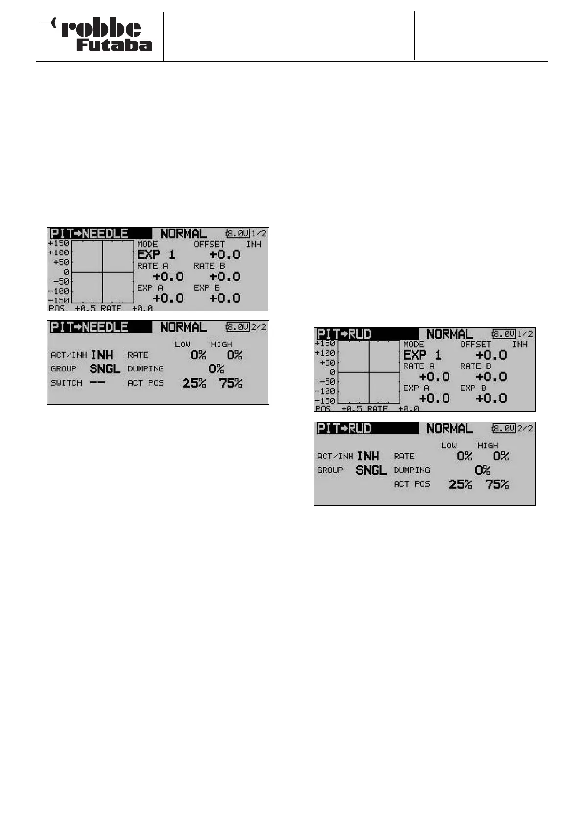
15.7 COLLECTIVE PITCH -> NEEDLE VALVE MIXER
This function is used to program an automatic needle valve
adjustment which follows the movement of the collective pitch
stick. It enables you to set the optimum fuel mixture at the car-
burettor (by adjusting the needle valve) whenever the load on
the motor alters due to changes in the pitch angle of the rotor
blades. An acceleration option can also be programmed to
o
ptimise this function.
Use the 3-D hot-key to mark the ‘COLLECTIVE PITCH ->
NEEDLE VALVE’ option in the Helicopter Model menu, and
confirm your choice with EDIT. The screen display has two
levels (pages), which look like this:
The mixer must first be activated in the second display in the
standard manner: mark the field, enter the setting using the ‘3-
D hot-key’, and conclude the activation with EDIT. The field will
now show ‘ON’ or ‘OFF’, according to the switch position.
The effects and method of setting the ‘Global’ or ‘Separate’
mode have already been described; the function is pro-
grammed in the ‘MODE’ line. A switch and its direction of ope-
ration can be defined in the ‘SWITCH’ column. The default set-
ting is ‘NONE’, i.e. the mixer is always switched on.
The mixer function itself is actually set up with the help of the
associated curve, which is set up in the familiar way: the first
step is to define the curve type: mark the ‘MODE’ field in the
topmost display, and make your selection using the ‘3-D hot-
key’. The method of programming the mixer curve is exactly
as described in Section 15.7 on page 67; please refer back to
that section if you are not sure.
An acceleration function can be programmed on the second
page of the menu (see also Section 15.3 on page 64). You can
enter a separate percentage value (Rate) for both maximum
travels of the collective pitch stick (Min. and Max.): mark the
field, enter the values required using the ‘3-D hot-key’, and
conclude the programming with EDIT. The setting is displayed
in the field as a percentage value. It is also possible to enter a
percentage value in the ‘Damping’ field; this determines how
long the function is to remain active once the change in setting
has been carried out. In the bottom line - ‘ACT-POS’ - you can
define a point for both sides which represents the position
from which the function is to take effect: mark the appropriate
field, enter the setting using the ‘3-D hot-key’, then conclude
the procedure with EDIT.
15.8 COLLECTIVE PITCH -> TAIL ROTOR (REVOLUTION)
MIXER
The purpose of this function is to detect torque fluctuations at
the main rotor, caused by changes to the throttle or collective
pitch settings, and pass that information to a mixer which con-
t
rols the tail rotor servo, so that the tail rotor always generates
the appropriate corrective torque, thereby more or less elimi-
nating unwanted moments around the vertical (yaw) axis. If
this mixer is set up accurately, it greatly eases the task of the
tail rotor gyro system. However, an incorrectly set mixer of this
type (also known as a Revo mixer) will interfere with the gyro’s
proper function. For this reason it is particularly important to
set up this mixer as accurately as possible. An acceleration
function can be programmed to optimise the function.
If a modern gyro is installed, and operated in heading-hold /
AVCS mode, the revolution mixer must always be switched off.
Use the 3-D hot-key to mark the COLLECTIVE PITCH -> TAIL
ROTOR option in the Helicopter Model menu, and confirm
your choice with EDIT. The menu has two levels (pages), which
look like this:
The mixer must first be activated on the second page of the
menu: simply mark the field, enter the setting using the ‘3-D
hot-key’, and conclude the activation with EDIT. The field now
displays ‘ON’ or ‘OFF’, according to the position of the switch.
The effects and method of setting the ‘Global’ or ‘Separate’
mode have already been described; the function is pro-
grammed in the ‘Mode’ field.
The mixer function itself is actually set up in the usual way with
the help of the associated curve: the first step is to define the
curve type: mark the ‘MODE’ field in the topmost display, and
make your selection using the ‘3-D hot-key’. In most cases a
linear curve is ideal for the Revolution mixer. The method of
programming the mixer curve is exactly as described in
Section 15.2 on page 63; kindly refer back to that section if
you are not sure.
Please be extremely cautious when making these adjust-
ments, and carry out any changes in small steps. Check all the
settings very carefully before eventually moving on to very
careful test-flights. From a stable hover the helicopter should
exhibit no tendency to rotate around the vertical (yaw) axis
when you open the throttle or increase the collective pitch set-
ting - whether you make the change quickly or slowly. The
reverse also applies: the helicopter must not rotate around the
68