Order No.
35 MHz: F 8042
40 MHz: F 8043
41 MHz: F 8044
FX-30
12.5 FUNCTION
The transmitter employs a new method of selecting the model
type as basis for the mixer functions and transmitter control
arrangement (stick mode), and this process automatically
generates the optimum configuration for the model type you
select. We recommend that you keep to this set-up if possible,
so that you are always using a standard configuration.
T
he “Function” menu clearly shows the output to which the
corresponding servo is connected, and which transmitter con-
trol is used to operate it. Where a single function operates two
or more servos, the corresponding transmitter controls are
configured accordingly. Within an individual model type the
configuration varies little, although the number of channels in
use may increase if the number of wing flaps and other control
surfaces is higher than normal.
T
he situation is different when you switch from one model type
to another. For example, if the model type changes from a nor-
mal tail to a tail layout with two elevator servos (Ailvator), the
sequence of functions is necessarily different. The same also
applies to model gliders (powered and unpowered), and for
flying wing models with and without winglets.
For the PCM-G3 system the second aileron output has been
shifted to output 5, in order to maintain compatibility with
small five-channel and six-channel receivers; the higher num-
ber of channels has also necessitated this change. This means
that the receiver channel sequence is not the same as that of
the PCM 1024 / PPM 8 system. However, you can select any
function sequence you like in this menu, in order to maintain
compatibility with the PCM 1024 and PPM 8 system.
Note:
If you need to change the function sequence when using the
PCM-G3 system, please ensure that associated functions are
allocated together within the channel groups 1 … 6 or 7 … 12.
Do not assign paired functions to channels 6 and 7, as this
could result in different servo transit times.
The servo sequence tables are to be found in Sections 5.1 to
5.4 (Servo sockets); see pages 14 to 17 in these instructions.
ASSIGNING TRANSMITTER CONTROLS
Use the 3-D hot-key to mark the ‘Function’ set-up menu in the
Linkage menu, and confirm your choice with EDIT. The follo-
wing screen display now appears:
There are additional screen pages of this kind; the page indi-
cator on the right-hand side indicates this. In this menu you
can assign your preferred transmitter controls and trims for all
functions, and determine the sequence of functions.
Any transmitter control can be assigned to any control func-
tion:
• First mark the ‘FUNCTION’ field using the 3-D hot-key,
then confirm it with EDIT.
• Then mark the appropriate function field, e.g. ‘ELEVATOR’
for elevator, and confirm it.
• Now select the transmitter control you wish to use for this
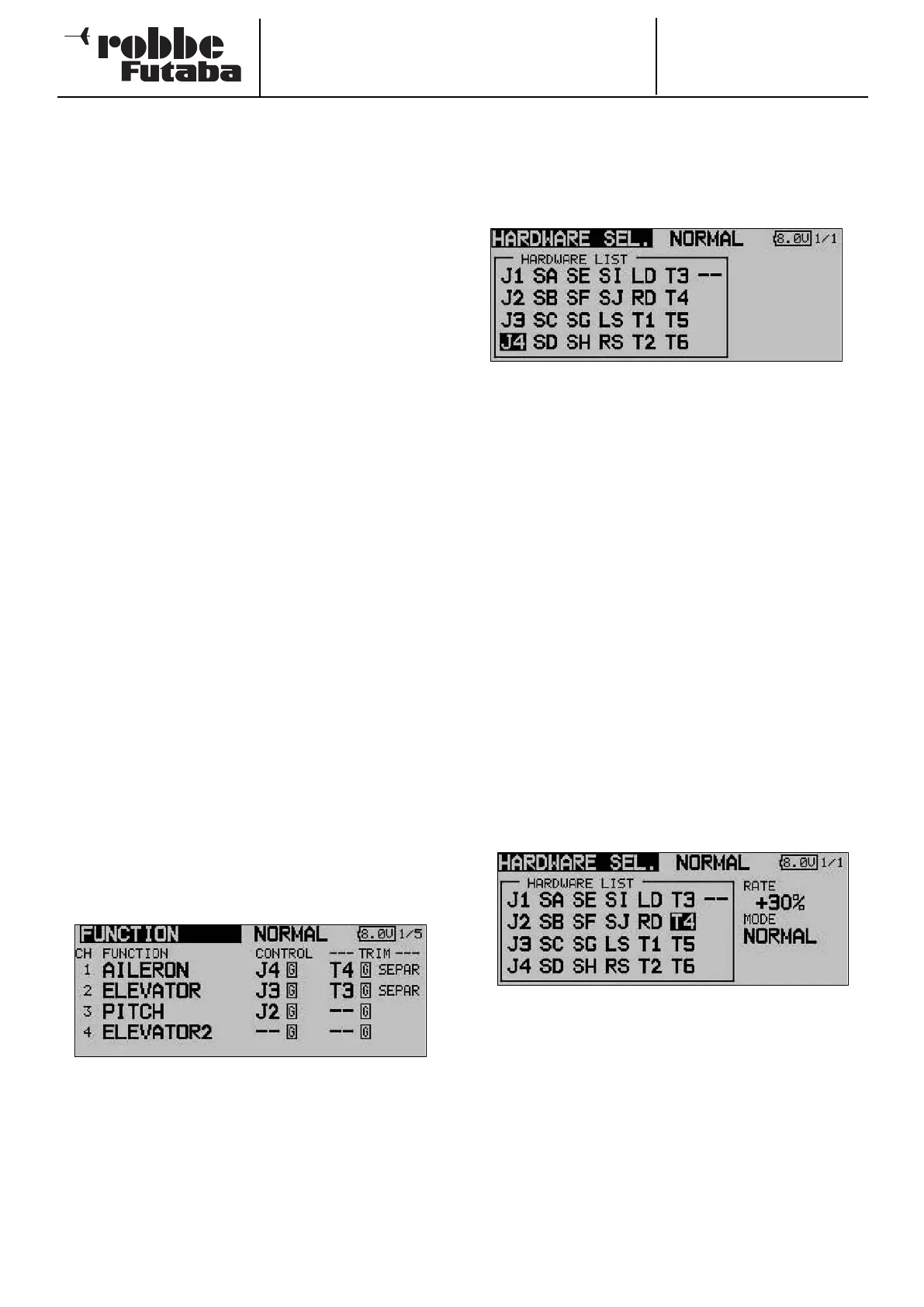
function: mark the ‘HARDWARE SEL.’ field and activate it.
The display changes, and a Select menu appears which
lists the transmitter’s controls in symbolic form:
• At this point you can now assign your choice of transmit-
ter control to the selected function by moving the flashing
cursor using the 3-D hot-key and confirming with the
‘EDIT’ button.
• The ‘Global’ and ‘Separate’ fields determine whether the
transmitter control is to be the same for this function in all
flight modes (Global). If you set the function to ‘Separate’,
the transmitter control for this function can be different for
each flight mode (condition). This point is selected by tur-
ning the ‘3-D hot-key’ to left or right; the display changes
when you operate the selected flight mode change-over
switch. A combination of ‘Global’ and ‘Separate’ transmit-
ter controls is also possible.
SELECTING THE TRIM CONTROLS
The trim controls are also freely selectable; the procedure is
identical to that for selecting the transmitter controls. Mark the
‘TRIM’ field for the corresponding function and confirm your
choice; the Trim set-up menu now appears.
In this menu you can select the trim controls from the symbo-
lic depictions on the left-hand side of the screen, and assign
them in any way you wish.
TRIM SETTINGS
Additional adjustments can be carried out in this menu:
• Trim Rate
The trim travel is infinitely variable within the range -150 to
+150% of the travel of the transmitter control; the default
setting is +30%. Once you have marked and activated this
option, you can set the desired % value by turning the ‘3-
D hot-key’. You can revert to the default setting (30%) by
holding the ‘EDIT’ button pressed in for at least one
second.
31