Order No.
35 MHz: F 8042
40 MHz: F 8043
41 MHz: F 8044
FX-30
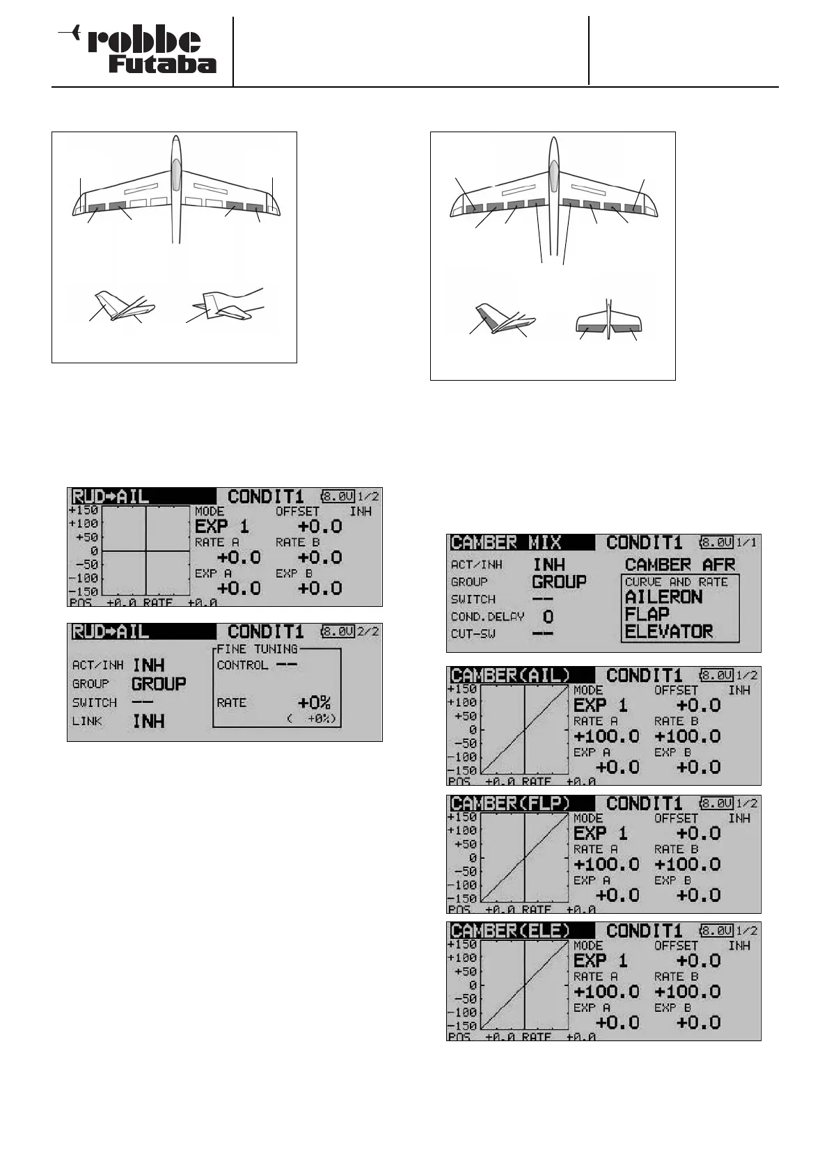
14.7 RUDDER -> AILERON MIXER
This menu is
used for setting
up a mixer
which causes
the ailerons to
move in the
d
irection of the
turn when a rud-
der command is
given.
This function is
employed pri-
marily with
l a r g e - s c a l e
m
odel aircraft
where a scale control system is required, i.e. emulating a full-
size aircraft. However, the same mixer can also be useful when
flying particular manoeuvres in a 3-D aerobatic schedule.
Use the 3-D hot-key to mark the ‘Rudder -> aileron’ mixer in
the Model menu, and confirm your choice with EDIT. The menu
has two levels (pages), which look like this:
The function must first be activated in the ‘ACT / INA’ line, as
previously described: first mark the field, enter the settings
using the ‘3-D hot-key’, and conclude the activation with EDIT.
In the field you will see ‘ON’ or ‘OFF’ according to the position
of the switch.
The effects and settings for the programming of ‘Global’ or
‘Separate’ mode have already been described repeatedly;
they are altered in the ‘Mode’ line. In the ‘Switch’ line a switch
can be selected in the familiar manner, and its direction of ope-
ration determined. The default setting here is ‘NONE’, i.e. the
mixer is always switched on.
A mixer curve can be set up and programmed on the first page
of the menu in the usual manner. This mixer curve determines
the rate of following, i.e. the extent to which the ailerons move
when a rudder command is given.
On the second page of the menu the fine-tuning settings can
be carried out in the separate frame marked ‘Fine Trim’. The
fine-tuning settings are entered using the method described
for the aileron - rudder mixer on page 49.
14.8 SPOILER
The purpose of
this menu is to
set up a mixer
which causes
a
ll the wing
flaps to be
lowered to
increase wing
camber and
thereby maxi-
mise lift.
The travels for
a
ll the control
surfaces can be
set in the ‘up’ or
‘down’ direction
as required, to ensure that the mixer can generate the opti-
mum wing geometry for all flight tasks. The servo travels and
directions of rotation can be set accurately using a mixer
curve. It is also possible to program a delay time, define the
servo transit speed and select a mixer trigger switch.
Use the 3-D hot-key to mark the ‘Spoiler’ option in the Model
menu, and confirm your choice with EDIT. The menu has four
levels (pages), which look like this:
The adjustment facilities are extremely comprehensive, but
they are arranged in just as logical a manner as all the other
menus described up to this point.
52
Main
a
ileron
(AIL2)
Winglet
(RUD)
Chip
aileron
(
AIL4)
Chip
aileron
(AIL3)
Main
aileron
(AIL)
ELEVATOR
V-tail Normal tail
RUDDER
Winglet
(RUD2)
Chip
aileron
(AIL3)
Main
aileron
(AIL1)
Brake
flap
(BRFL)
Brake
flap
(BRF2)
Brake flaps
(BRF3 & 4)
Main
aileron
(AIL2)
Chip
aileron
(AIL4)
V-tail Ailvator
ELEVATOR
ELE
RUDDER
ELE2