Order No.
35 MHz: F 8042
40 MHz: F 8043
41 MHz: F 8044
FX-30
8
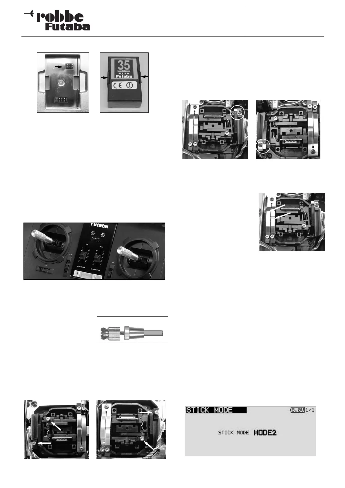
4.3 INSERTING / REPLACING THE RF MODULE
• Always switch the transmitter off before inserting the RF
module.
• Position the RF module squarely before pushing it into
place; press it in until the side lugs engage.
• Take care that no pins are bent when you insert the conne-
c
tor.
• To remove the RF module squeeze the side lugs inwards
and pull it out, keeping it straight and “square”.
4.4 STICK ADJUSTMENTS
The FX-30 transmitter is fitted with new precision dual-axis
stick units featuring quadruple ballraces and industrial-stan-
dard long-life potentiometers.
In designing these sticks we placed particular emphasis on
smooth, accurate control around the centre position.
ADJUSTING THE STICK LENGTH
The length of the primary sticks is infinitely variable, and can be
adjusted to suit the pilot’s preference.
• Loosen parts A and B
• Set the stick-top to the des-
ired length
• Lock part B against part A.
CENTRING FORCE ADJUSTMENT
On both stick units the centring force of the springs is infinitely
variable, and can be adjusted to suit your personal preference.
The first step is to remove the transmitter back panel. Adjust
the centring spring force at the positions indicated using the 1.5
mm A/F allen key supplied.
Part A Part B
4
.5 CONVERTING THE THROTTLE FUNCTION
As supplied, the transmitter is set up in Universal mode, i.e.
both sticks have a self-neutralising action.
Most users will wish to convert one of the two sticks to a rat-
chet or brake function in the vertical plane, to produce a non-
neutralising function for the throttle channel.
The first step is to locate a small bracket in the transmitter
accessory bag. Attach the bracket as shown, using the spring
force adjustor screw; this raises the return spring.
--
--
You can now activate the ratchet or brake spring and adjust the
force using the 1.5 mm A/F allen
key supplied.
ACTIVATING THE RATCHET FUNCTION
For fixed-wing model aircraft applications the throttle stick is
usually employed with a ratchet spring. The ratchet is applied
by carefully tightening the ratchet spring screw (rotating it to the
right) until the throttle stick “feels” right to you. Take care not to
activate the brake function at the same time; you may need to
unscrew the brake spring screw slightly.
ACTIVATING THE BRAKE FUNCTION
• The ratchet function should first be disabled by unscrewing
the ratchet spring.
• Now tighten the brake spring carefully (to the right) until the
throttle brake “feels” right to you.
The ratchet and brake function cannot be activated at the
same time, as they effectively overlap.
The stick mode is selected in the Transmitter Control Settings /
Stick Mode sub-menu of the System menu. If you convert the
throttle function, you will also need to check the stick mode and
change it if necessary (stick mode 1 to 4). The default software
setting is Stick Mode 2 (throttle left); see also the System Menu,
page 23.
Raised centring spring for
throttle right (modes 1 + 3)
Raised centring spring for
throttle left (modes 2 + 4)
Brake
Ratchet