Order No.
35 MHz: F 8042
40 MHz: F 8043
41 MHz: F 8044
FX-30
14.14 GYRO SETTINGS
Gyros are often used in modern fixed-wing model aircraft in
order to stabilise one flight axis, and this is the menu to use for
entering the settings for the gyro. The basic purpose of this
facility is to allow the pilot to set three different modes (Normal
- AVCS) and the corresponding gyro gain (sensitivity) for a
maximum of three gyros, which can then be called up simply
b
y operating a switch at the transmitter.
Gyro gain can be programmed as a percentage value, and it is
also possible to select the gyro type. You can assign a switch
which is used to set the gain to any of three values from the
transmitter.
It is also possible to determine whether the settings are to
apply to all flight modes (Global) or only to the currently acti-
vated flight mode (Separate).
U
se the 3-D hotkey to mark the ‘Gyro’ option in the Model
menu, and confirm your choice with EDIT. The screen now
looks like this:
The menu features three identical levels (pages) which can be
used for three different settings per flight mode, which can be
called up when required.
Start by activating this function in the ‘ACT / INA’ line by mar-
king the field, then set the values using the ‘3-D hot-key’.
Conclude the activation process with EDIT. The field will then
switch to ‘ON’ or ‘OFF’, according to the position of the
switch.
In the ‘Type’ column you should enter the type of gyro instal-
led in the model. For AVCS or ‘heading hold’ gyros enter ‘GY’
as the type; for others select the ‘NORMAL’ type. In the
‘Switch’ column you can select a switch and its direction of
operation using the familiar procedure. The default setting is
‘NONE’, i.e. the function is constantly switched on. The effects
and method of setting the ‘Global’ or ‘Separate’ mode have
already been described; the setting is adjusted in the ‘Mode’
line.
In the ‘MODE’ column you have the option of choosing whet-
her the gyro is to work in ‘AVCS’ mode (heading hold) or nor-
mal mode. For more information on this, please refer to the
instructions supplied with the gyro you have installed in the
model. The gain for the three (possible) gyros is entered in the
usual way as a percentage value.
Note:
If you wish to be able to use a transmitter control to adjust
gyro gain from the transmitter, Gyro 2 or Gyro 3 mode must be
activated under ‘Functions’ in the Base menu.
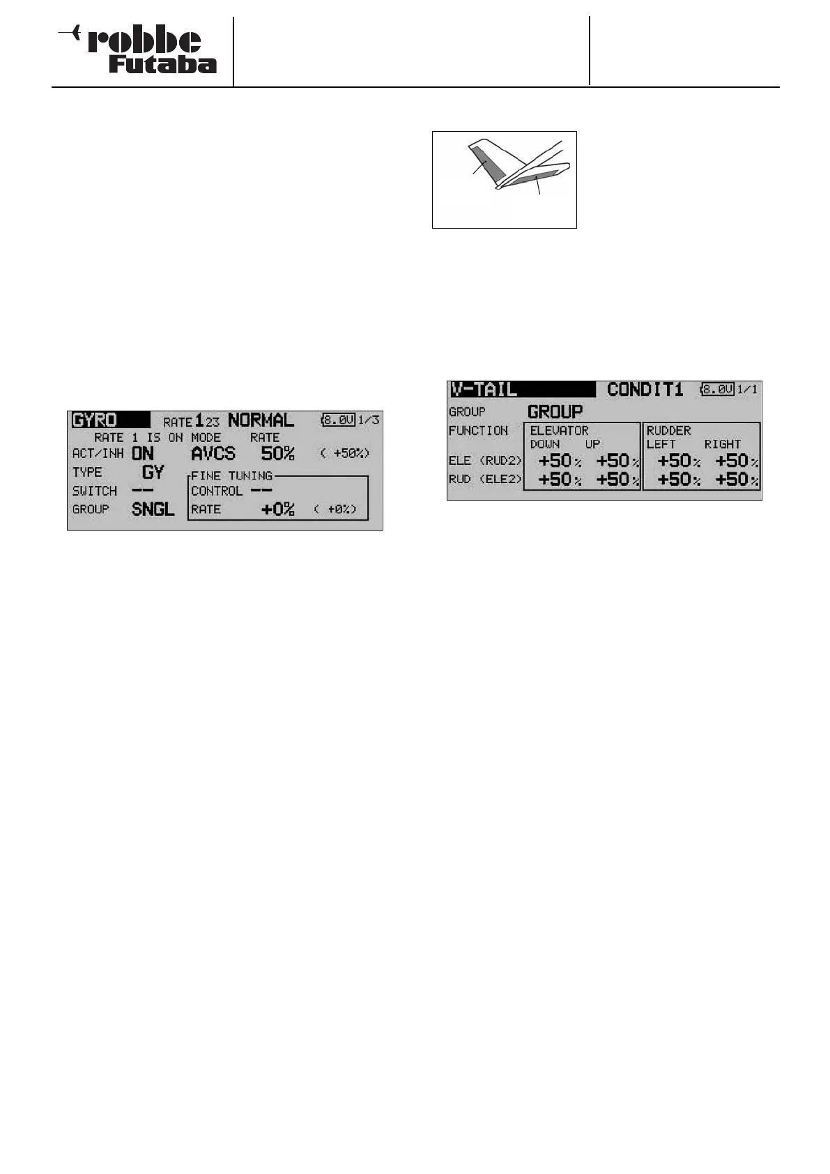
14.15 V-TAIL MIXER
This menu presents all the mixer
functions required for controlling
a V-tail, which involves superim-
posing the signals from the rud-
d
er and elevator controls at the
transmitter. The travels of the ele-
vator function (same-sense
movement) and of the rudder function (opposite-sense move-
ment) can be adjusted independently of each other. The
sketch shows the arrangement of the functions for a typical V-
tail.
Use the 3-D hot-key to mark the ‘V-tail’ option in the Model
m
enu, then confirm your choice with EDIT. The screen display
now looks like this:
The first step is to define the mode (‘Global’ or ‘Separate’) in
the ‘Mode’ line in the usual way.
The servo travels for both control surfaces of the V-tail can
now be set separately for the elevator and rudder functions in
the form of percentage figures. The same applies to the dire-
ctions of movement; this procedure has already been descri-
bed in full many times in these instructions: first mark and con-
firm the appropriate field, then enter the percentage value
using the ‘3-D hot-key’, and conclude the procedure with
EDIT.
The default setting in each case is 50%. Holding the ‘EDIT’
button pressed in for at least one second restores the default
setting.
Once you have entered the data, it is essential to carry out a
check using the model itself, to ensure that the V-tail mixer is
operating correctly, and that all the settings are as required.
Check also that the total travel is not excessive, i.e. that the
system is not restricted or obstructed mechanically in any way.
58
Elevator
Rudder