Order No.
35 MHz: F 8042
40 MHz: F 8043
41 MHz: F 8044
FX-30
16. TRANSMITTER CONTROL / SWITCH SELECT MENU
The software of the FX-30 includes a comprehensive
Transmitter Control Select menu, which allows you to select
any transmitter control you like for virtually all the functions -
whether to act as a control for a switched function, or for a
proportional control function.
The Select menu always looks the same, and the description
presented here relates to both options.
A
s soon as you mark a field for selecting a transmitter control
or switch for a particular function, and confirm your choice
with EDIT, the following Select menu appears. Please note at
this point that the menu differs from function to function, i.e.
the display and selectable options vary according to the appli-
cation.
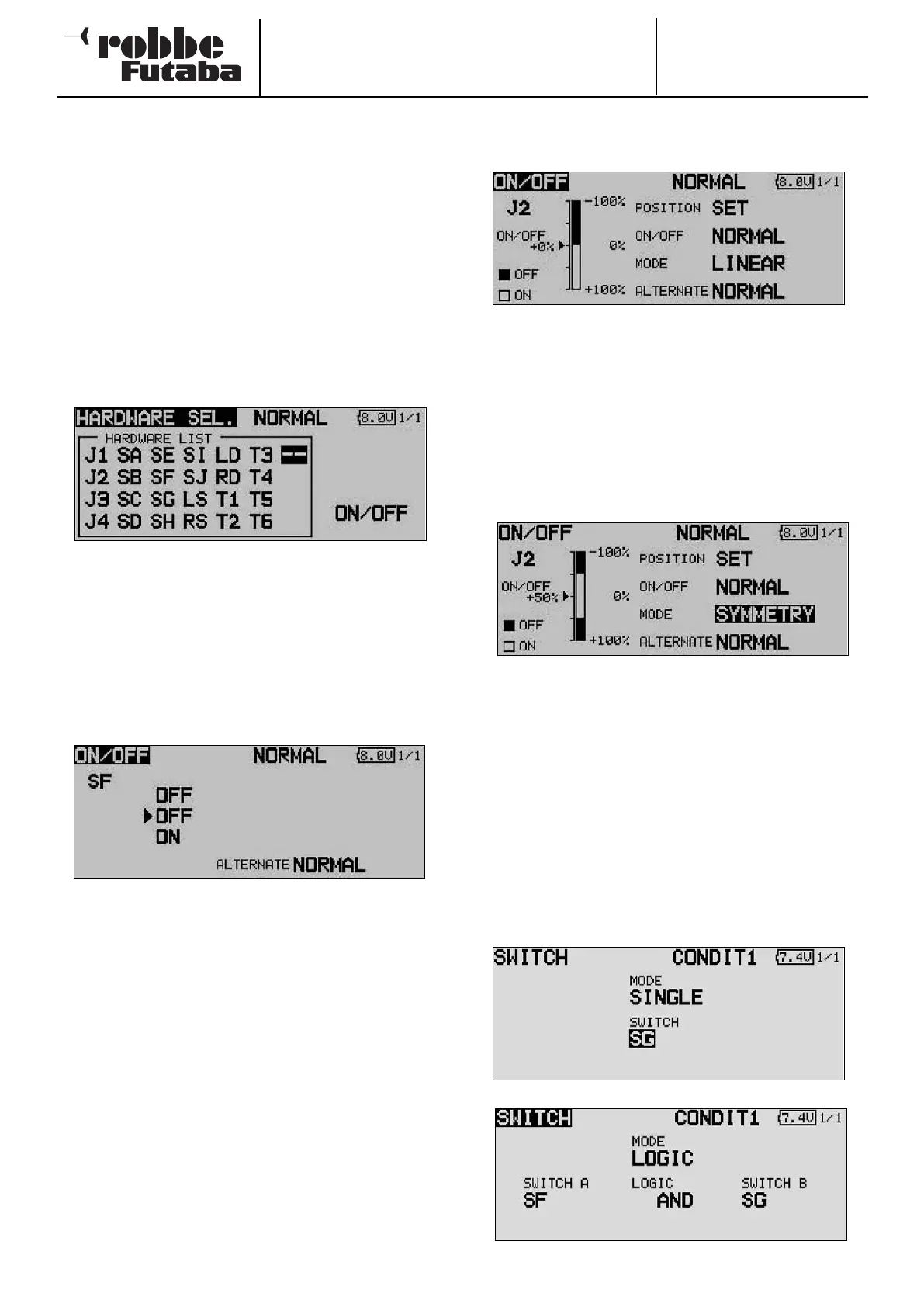
Our example shows the Switch Select menu for the
‘Programmable Mixer’ function. All the transmitter controls,
switches and rotary trimmers are listed and named.
J1 … J4 = Stick 1 … 4
SA … SH = Switch A … H
SI … SJ = Stick switch, right / left
LD … RD = Left / right rotary knob
LS … RS = Left / right linear slider
ON / OFF = Switch position
T1 … T6 = Rotary trimmer
Mark the desired switch or control, and confirm your choice
with the ‘EDIT’ button.
When you have selected a switch, move the cursor to the ON
/ OFF field, and define the switch position.
A sub-menu now appears in which you can define the switch
position; in our example for switch ‘G’.
• The arrows indicates the current mechanical position of the
switch. Use the 3-D hot-key to change the ON or OFF
position in order to set the desired direction of switching.
• In the bottom part of the display the switch type is deter-
mined: press-button (Memory) or ratchet switch (NOR-
MAL).
• The upper part of the screen display shows the current
flight mode. If the function is to be controlled by different
switches or transmitter controls in different flight modes,
the mode must be changed to Separate. It will then be
necessary to switch the flight mode in this menu, and
select another switch or control for the current flight mode.
If you choose a primary stick or other proportional control, you
can set the switching point in the following screen.
• SET
To set the trigger point, move the selected transmitter control
to the desired switching point, move the cursor to SET, and
press the EDIT button. The switching point is displayed as a %
value and in bar-graph form.
• ON / OFF
At this menu point you can define the direction of switching:
NORMAL or REVERSE.
• MODE
LINEAR
At this setting the transmitter control travel is divided up into
an ON zone and an OFF zone (see screen shot above).
The function is then switched on or off according to the posi-
tion of the transmitter control.
SYMMETRICAL
The two switching points at this setting are located symmetri-
cally relative to the stick’s neutral position. A switched function
is triggered as soon as the value exceeds the switching point
at the top or bottom end of the stick travel.
MEMORY
The switch type - push-button (Memory) or ratchet switch
(NORMAL) - is selected in the bottom part of the screen.
• Logic functions
Particular functions and flight modes can also be switched on
and off using a logical link between two switches; this is
known as a logic function.
Select the switch MODE (SINGLE) or a logic link (LOGIC).
The following functions are available:
• AND: Serial link between switches
• OR: Parallel link between switches
• EX-OR: Links and connects particular switches.
71