Order No.
35 MHz: F 8042
40 MHz: F 8043
41 MHz: F 8044
FX-30
75
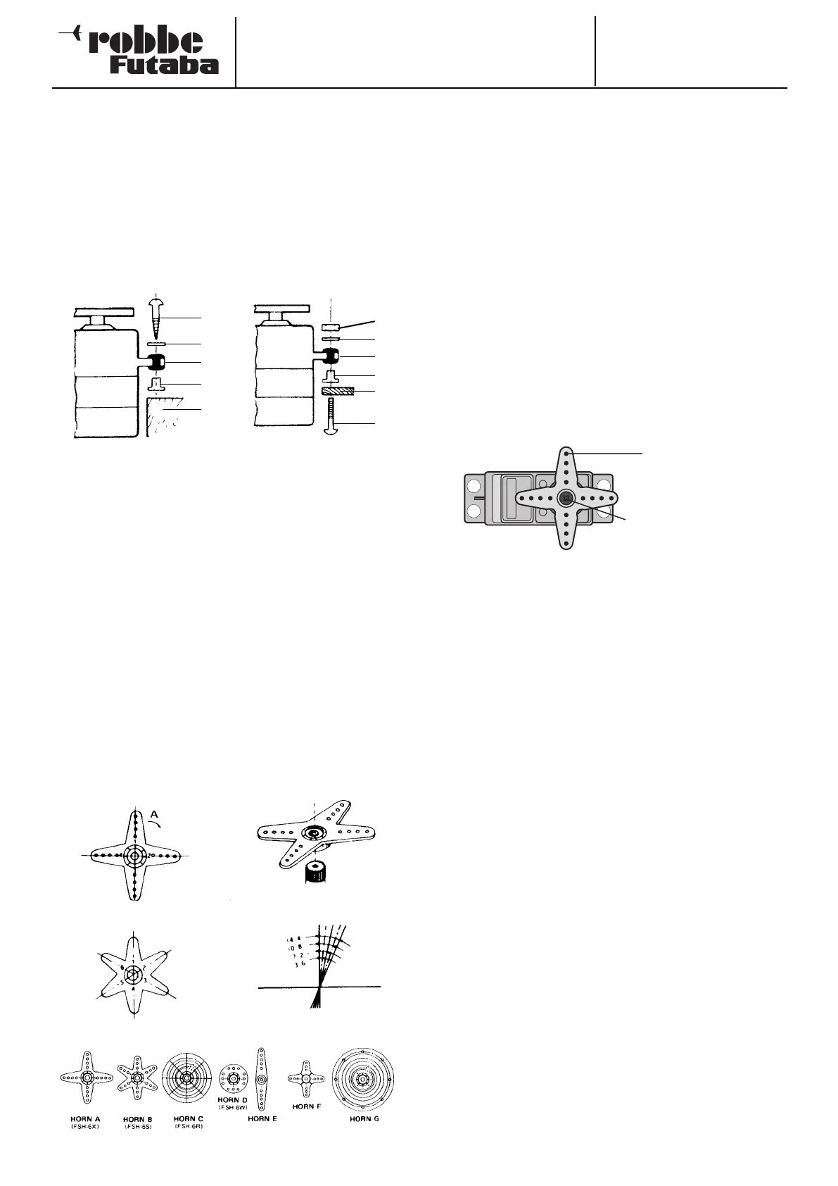
A range of different servo output arms is available for robbe
servos, and they are illustrated in the picture at the bottom of
the page. The drawing also shows the angular change per
individual spline segment.
S
ervos with splined output shafts permit fine mechanical
adjustment of the servo neutral position. The position is adjus-
ted as follows: first undo the retaining screw and lift off the
output device. Position the output device in the appropriate
neutral position, push it down onto the splined output shaft,
and re-tighten the retaining screw. The diagram below shows a
servo with pushrod connected.
18.7 INSTALLING LINKAGES
T
he basic rule when installing mechanical linkages and control
surfaces is that they must be extremely free-moving, other-
wise the servos will draw excessive currents, and the effective
operating time per battery charge will be greatly reduced. At
the same time the centring accuracy of the control system will
be worse, which in turn has a negative influence on the mode-
l’s flying characteristics.
Retaining
screw
Pushrod
18.5 INSTALLING SERVOS
When installing servos in a model, always use the rubber
grommets and tubular brass spacers (eyelets) supplied. When
you fit the servo retaining screws, ensure that they are not
tightened beyond the point where the brass eyelets make con-
t
act top and bottom; if the rubber grommets are compressed
to this point, they are no longer capable of absorbing vibration.
The following diagram shows two typical methods of mounting
servos.
Diagram “A” shows a wooden servo plate. Diagram “B” shows
the use of a plastic or aluminium plate.
In RC model cars the servos are usually fitted in the openings
provided for them in the RC installation plate. Robbe quick-
release servo mounts are a good choice for model boats. Ple-
ase take great care over mounting servos, as they are sensitive
to vibration.
18.6 SERVO TRAVEL / SERVO OUTPUT LEVERS
Each servo must be able to move through its full arc of travel
without being mechanically obstructed by the control surface
or its linkage. This applies in particular to the carburettor lin-
kage: the “full throttle” and “idle” settings must be determined
by the stick positions; never by the throttle’s mechanical end-
stop. If you ignore this warning, the servo motor will constantly
be under almost full load, and will consume an extremely high
current.
1 Nut
2 Washer
3 Rubber grommet
4 Metal spacer sleeve
5 Aluminium plate
6 Screw
1 Woodscrew
2 Washer
3 Rubber grommet
4 Metal spacer sleeve
5 Wood
1
2
3
4
5
1
2
3
4
5
6