Order No.
35 MHz: F 8042
40 MHz: F 8043
41 MHz: F 8044
FX-30
vertical (yaw) axis when you reduce motor torque or the colle-
ctive pitch setting.
An acceleration function can be programmed on the second
page of the menu (see also Section 15.3 on page 64). You can
enter a separate percentage value (Rate) for both maximum
travels of the collective pitch stick (Min. and Max.): mark the
field, enter the values required using the ‘3-D hot-key’, and
c
onclude the programming with EDIT. The setting is displayed
in the field as a percentage value.
It is also possible to enter a percentage value in the ‘Damping’
field; this determines how long the function is to remain active
once the change in setting has been carried out. In the bottom
line at ‘ACT-POS’ you can define a point for both sides which
represents the position from which the function is to take
effect: mark the appropriate field, enter the setting using the
‘
3-D hot-key’, then conclude the procedure with EDIT.
15.9 GYRO SETTINGS
This function is used for adjusting gyro gain (sensitivity) from
the transmitter. Gyro gain can be entered as a percentage, and
it is also possible to select the gyro type. You can assign a
switch for changing gyro gain to any of three settings (Rate 1,
2 or 3) for each flight mode. As with many functions, it is also
possible to determine whether the settings are to apply to all
flight modes or only to one mode (Global or Separate mode).
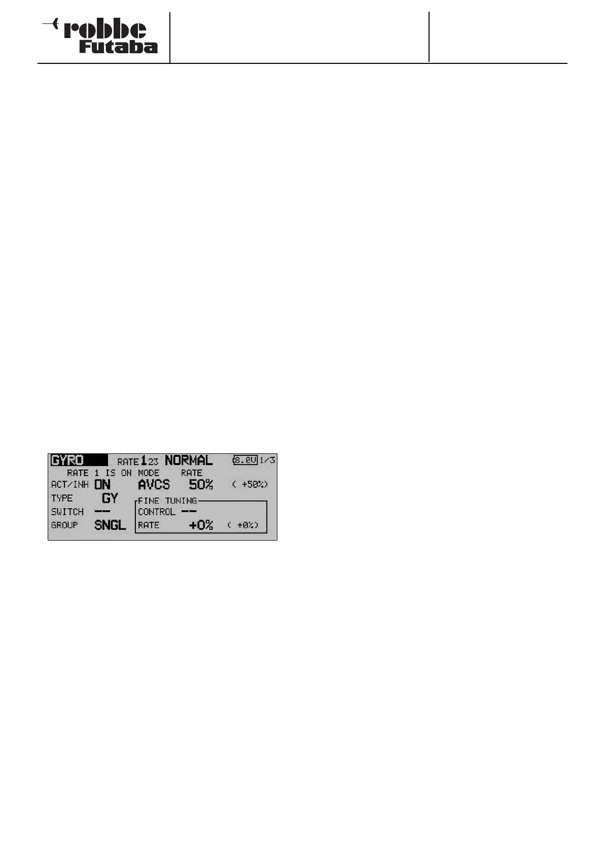
Use the 3-D hot-key to mark the ‘Gyro’ function in the Heli-
copter Model menu, and confirm your choice with EDIT. The
display looks like this:
The menu has three identical levels (pages) for setting three
different gyro gain values (Rate 1 to 3).
This mixer must first be activated in the ‘ACT’ line: first mark
the field, enter the setting using the ‘3-D hot-key’, and con-
clude the activation with EDIT. The field will then display ‘ON’
or ‘OFF’, according to the position of the switch.
In the ‘Type’ column you should enter the type of gyro fitted to
the model. For AVCS or ‘heading hold’ gyros enter ‘GY’ as the
type; for others select the ‘NORM’ type. In the ‘SWITCH’
column you can select a gyro gain switch and its direction of
operation using the familiar procedure.
The default setting is ‘NONE’, i.e. the function is constantly
switched on. The effects and method of setting the ‘Global’ or
‘Separate’ mode have already been described; the settings are
adjusted in the ‘Mode’ line.
In the ‘MODE’ column you have the option of choosing whet-
her the gyro is to work in ‘AVCS’ mode (heading hold) or nor-
mal mode. For more information on this, please refer to the
instructions supplied with the gyro you are using.
Under ‘FINE Trim’ you can enter the fine-tuning settings. A
transmitter control can be defined which is used as a means of
fine-tuning the mixer settings: first select your preferred trans-
mitter control in the ‘Transmitter control’ field. Mark the appro-
priate field, then use the ‘3-D hot-key’ to make your selection
in the Switch / Transmitter Control Select menu. Any of the
a
uxiliary transmitter controls can be selected. The current set-
ting and direction of operation are displayed on-screen.
Three different gyro settings can be called up for each flight
mode in this menu. If you have assigned a separate transmitter
control (linear slider) to the ‘Gyro’ function in the Functions
menu, so that you can override the set values, then this trans-
mitter control has no function; this arrangement avoids the
settings in the menu counteracting the transmitter control
p
ositions.
However, if you still wish to be able to adjust gyro gain in the
usual way using a slider, select the Gyro 2 function.
This function allows you to adjust gyro gain using a linear sli-
der.
Caution:
In this case we recommend that you enter no settings in the
Gyro menu, as the functions may interact, either by a cumula-
tive effect or by cancelling each other out.
69