Order No.
35 MHz: F 8042
40 MHz: F 8043
41 MHz: F 8044
FX-30
The function must first be activated in the ‘ACT / INA’ line, as
previously described: first mark the field, enter the settings
using the ‘3-D hot-key’, and conclude the activation with EDIT.
The field will now display ‘ON’ or ‘OFF’ according to the posi-
tion of the switch.
The effects and settings for the programming of ‘Global’ or
‘Separate’ mode have already been described repeatedly;
t
hey are altered in the ‘Mode’ line. In the ‘Switch’ line a switch
can be selected in the accustomed manner, and its direction of
operation determined. The default setting here is ‘NONE’, i.e.
the mixer is always switched on. You can program a delay time
for each channel, so that there is a smooth transition when you
switch modes, rather than an abrupt change. The first step
here is to mark the ‘DELAY’ line. You can now enter a setting
using the ‘3-D hot-key’, and confirm your choice with EDIT.
O
n the second page of the menu the AFR settings are entered
for the camber-changing flap mixer. This sub-menu is acces-
sed by marking the ‘Flap AFR’ field, and pressing the ‘EDIT’
button. The AFR curve is programmed exactly as described in
Section 14.2 on page 47.
The mixer curves can be set up and the servo travels entered
individually for the ailerons, the inner and outer brake flaps and
also for the elevators. In the separate ‘Curve and Rate’ field
the appropriate line must be marked and confirmed with EDIT.
On the next screen the mixer curve can be set up in the usual
manner, working separately for the left and right sides of the
curve. A vertical shift of the curve (Offset) is also possible.
The servo travels can be entered individually as percentage
values in a separate frame, e.g. for all four aileron servos sepa-
rately. In the same display the servo transit speed can also be
programmed; you can enter a speed separately for the ‘there’
and ‘back’ directions. The adjustment range is 0 to 27 incre-
ments. Please note: the higher the number, the more slowly
the servo moves. The maximum value (27 increments) corres-
ponds to a duration of nine seconds. The ‘3-D hot-key’ is used
to make any adjustments. The default value is always ‘0’. Hol-
ding the ‘EDIT’ button pressed in for at least one second res-
tores the default setting.
Please note that the programming options and the actual
appearance of the screen display may vary slightly according
to the model type and wing type you have selected.
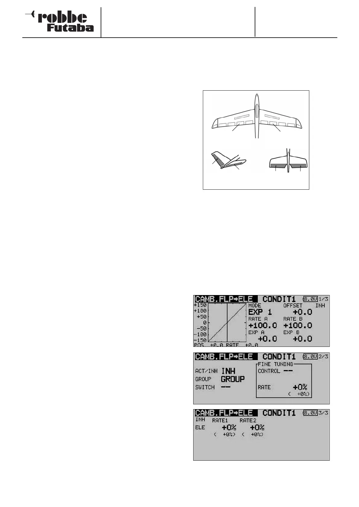
14.9 CAMBER-CHANGING FLAP -> ELEVATOR MIXER
This menu is used for setting up a mixer which causes all the
wing flaps to be lowered or raised to change the wing camber
when an elevator command is given. This amplifies the eleva-
tor effect, and enables the aircraft to turn more tightly and per-
f
orm “square” manoeuvres.
A mixer curve can be programmed for this function, and it can
be activated using a switch which is user-selectable. As with
many functions, it is also possible to determine whether the
settings are to apply to all flight modes (Global) or only to the
currently activated flight mode (Separate). You can define an
auxiliary transmitter control which is used to fine-tune the
function.
Use the 3-D hot-key to mark the ‘Flap -> Ele’ option in the
Model menu, and confirm your choice with EDIT. The menu
has three levels (pages), which look as shown below.
The function must first be activated in the ‘ACT / INA’ line, as
previously described: first mark the field, enter the settings
using the ‘3-D hot-key’, and conclude the activation with EDIT.
The field will now display ‘ON’ or ‘OFF’ according to the posi-
tion of the switch.
53
Left camber-
changing flap
(CAMBER)
Right camber-
changing flap
(CAMBER2)
RUDD
ELE
ELE2
ELE2
V-tail Ailvator