Order No.
35 MHz: F 8042
40 MHz: F 8043
41 MHz: F 8044
FX-30
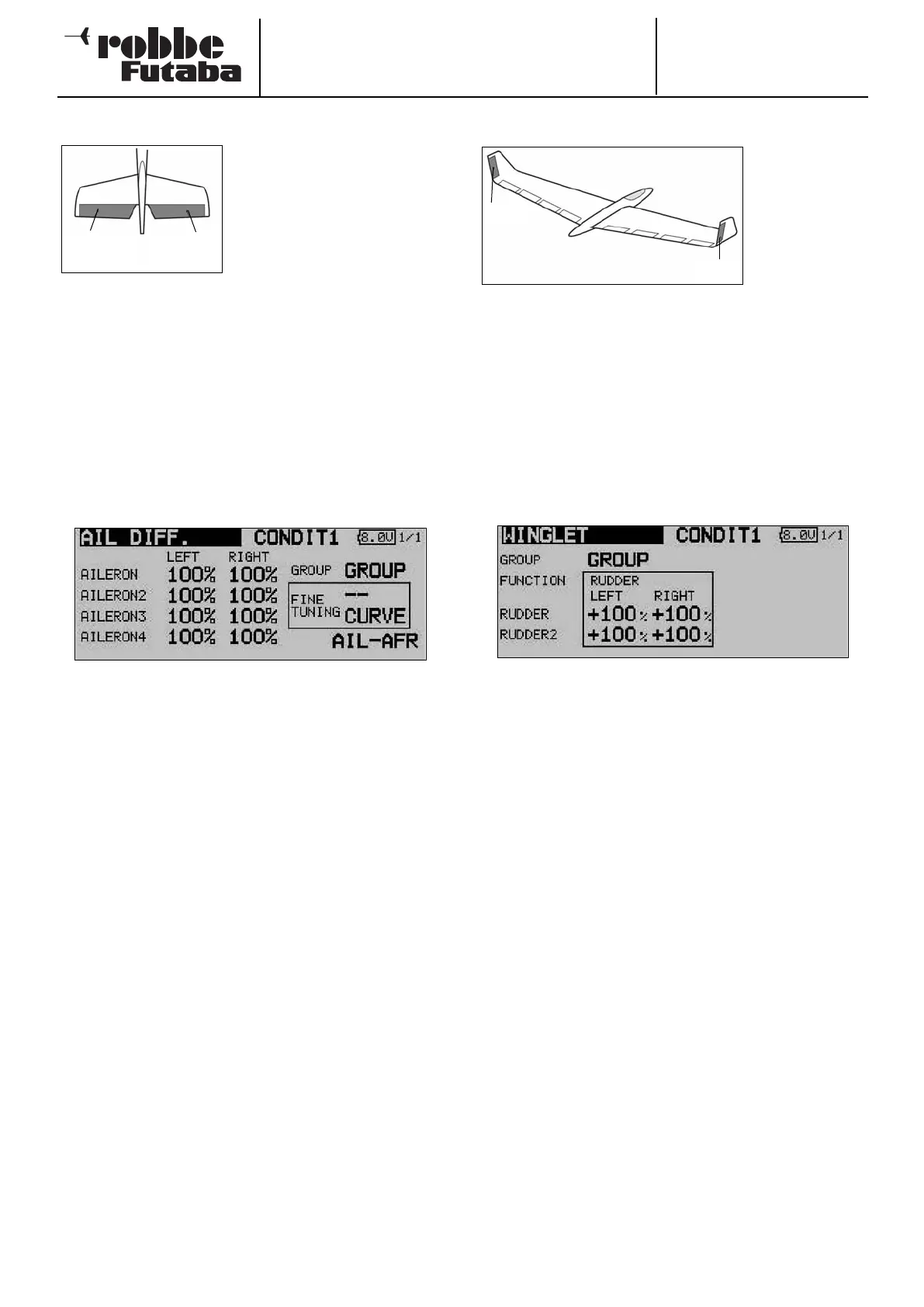
14.16 ELEVATORS WITH AILERON FUNCTION
This menu presents all the mixer
functions required for controlling
a pair of elevators which are also
used to generate a rolling
moment (around the longitudinal
axis) to amplify the effect of the
w
ing-mounted ailerons, i.e. both
elevator panels deflect in parallel
with the ailerons.
The purpose of this option is to provide an effective increase
in the roll rate of a fixed-wing model aircraft. The mixer can
only be used if the model is fitted with two elevator servos,
each connected to a separate receiver output. The function is
sometimes called an ‘Ailvator’ system. It can be used with nor-
m
al tails and also for models with a V-tail (ruddervator). The
drawing shows the arrangement of the functions in the case of
a conventional tail.
Use the 3-D hot-key to mark the ‘Aileron differential’ option in
the Model menu, and confirm your choice with EDIT. The
screen now looks like this:
The first step is to define the mode (‘Global’ or ‘Separate’) in
the usual way
The servo travels for both control surfaces of the V-tail can be
set separately for the elevator and aileron functions in the form
of percentage figures. The same applies to the directions of
movement; this procedure has been described in full many
times: first mark and confirm the appropriate field, then enter
the percentage values using the ‘3-D hot-key’ before conclu-
ding the procedure with EDIT.
The default setting in each case is 100%. Holding the ‘EDIT’
button pressed in for at least one second restores the default
setting.
Once you have entered the data, it is essential to carry out a
check using the model itself, to ensure that the AILVATOR
mixer is operating correctly, and that all the settings are as
required. Check also that the total travel of the aileron and ele-
vator functions is not excessive, i.e. that the system is not res-
tricted or binds mechanically at any point.
Note:
If the second elevator function is only required to work as a
simple elevator, i.e. without superimposed aileron travel, we
recommend that you set the aileron value to 0%.
14.17 WINGLET RUDDER SETTINGS
This menu pre-
sents all the
mixer functions
required for con-
t
rolling rudder
panels in the
winglets of a
fixed-wing
model aircraft.
These control surfaces have the same effect as a conventional
rudder, but tend to be more effective since they are not located
in the turbulent airflow from the propeller. This reduces drag,
and therefore helps to improve flight performance.
The function is primarily employed on flying wing models with
tip-mounted winglets. The sketch shows the arrangement of
the functions.
Use the 3-D hot-key to mark the ‘Winglet’ option in the Model
menu, and confirm your choice with EDIT. The screen display
now looks like this:
The first step is to define the mode (‘Global’ or ‘Separate’) in
the usual way.
The servo travels for both winglet rudders can now be set
separately for Rudder and Rudder 2, in the form of percentage
figures. The same applies to the directions of movement; this
procedure has already been described in full several times:
first mark and confirm the appropriate field, then enter the per-
centage value using the ‘3-D hot-key’; conclude the procedure
with EDIT.
The default setting in each case is 100%. Holding the ‘EDIT’
button pressed in for at least one second restores the default
setting.
Please note that this function is only available if you have alre-
ady selected the appropriate model type (flying wing / delta).
59
Elevator
(Ail 5)
Elevator 2
(Ail 6)
RUD1
RUD2