Order No.
35 MHz: F 8042
40 MHz: F 8043
41 MHz: F 8044
FX-30
13.4 PROGRAMMABLE MIXERS
The FX-30 features ten freely programmable mixers which are
available for every model memory, in addition to the fixed pre-
programmed mixer functions. The programmable mixers fea-
ture user-selectable transmitter control settings which can be
called up, ranging from a linear characteristic to a nine-point
curve; the latter can be expanded to seventeen points for spe-
c
ial purposes.
The primary use of these mixers is to compensate for inter-
actions between the individual functions of fixed-wing model
aircraft, e.g. for precision aerobatic flying. When the corrective
mixers are properly set up, the model becomes generally sim-
pler and more pleasant to fly. Programmable mixers can be set
up to link any functions and channels (Master and Slave chan-
nels).
Three curve types are available for the transmitter control set-
tings: two exponential and one linear. All these mixers can be
assigned a separately variable delay, in order to avoid abrupt
transitions when a mixer is switched on in flight. Another
option is to set group mode (effective in all flight modes) or sin-
gle mode (effective only in a specific flight mode).
The trim select function determines whether the trim of the
Master channel is also to affect the Slave channel. The Offset
option allows you to adjust the mixed (slave) channel to match
the main function, so that there is no control surface move-
ment at the neutral position. The switches or other transmitter
controls which are used to activate the various mixers can be
selected individually. Finally, it is even possible to define a
transmitter control which is used to fine-tune the settings.
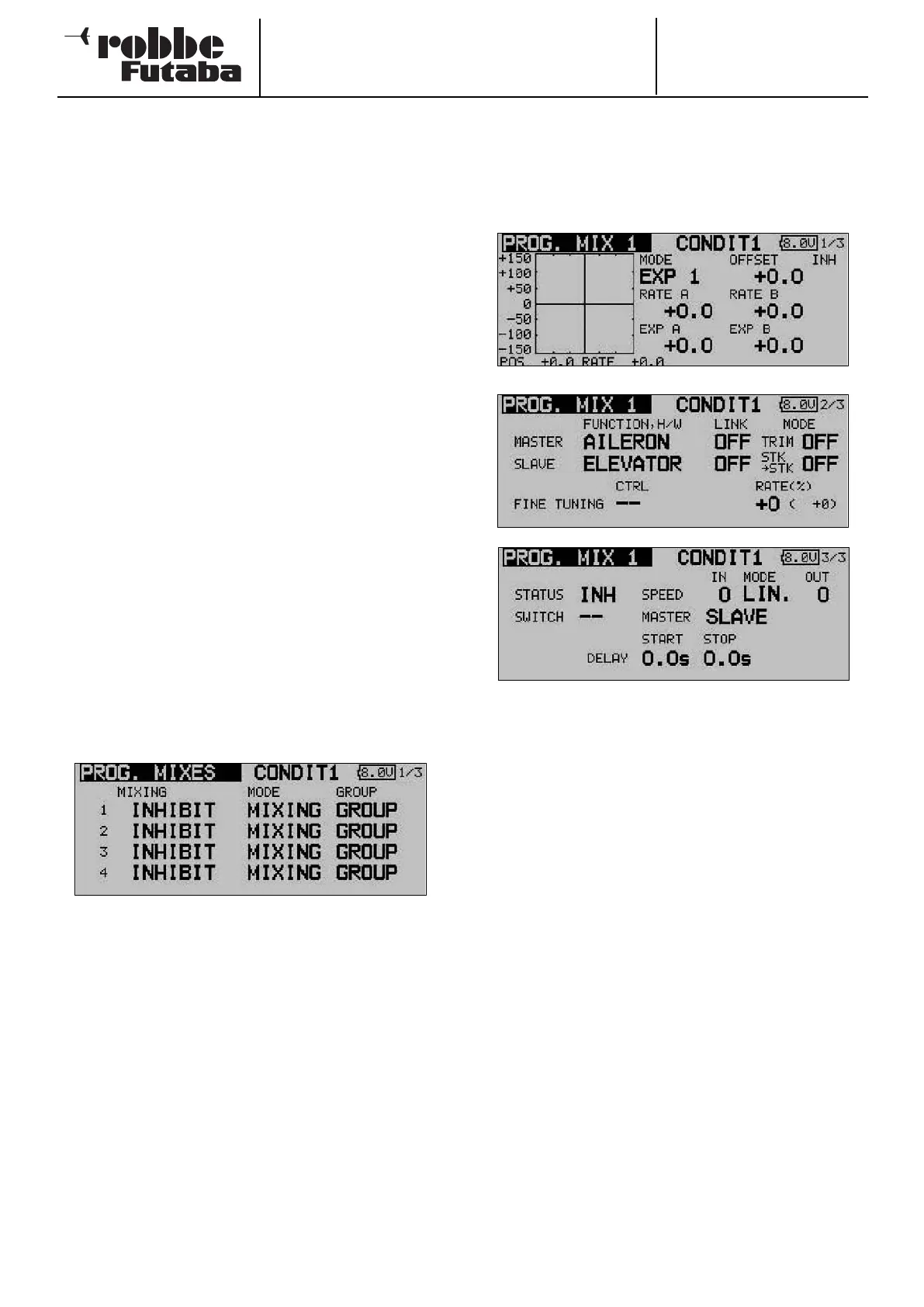
Use the 3-D hot-key to mark the ‘PROG. MIX’ option in the
Model menu, and confirm your choice with EDIT. The screen
now typically looks like this:
The individual mixers are listed line by line: the first four mixers
are listed on the first page. The display has additional levels
(pages); the page indicator on the right-hand side indicates
this. The programming procedure is described here using the
first mixer as an example, but mixers 2 to 10 are set up in
exactly the same way.
This menu is used to enter your preferred settings for the mixer
in question. In the last column ‘Global’ you can define whether
the mixer is only to apply to one flight mode (Separate) or to
all flight modes globally (Global); ‘global’ mode is the default
setting. To change this setting, use the 3-D hot-key to mark
the field for the mixer you wish to program. The field is now
highlighted (dark background), and you can turn the ‘3-D hot-
key’ to the left to change the setting to ‘Separate’. Activate the
change by pressing the ‘EDIT’ button.
You move to the actual programming masks by marking the
appropriate field in the ‘Mixer’ column on the left, and confir-
ming with the ‘EDIT’ button. The display changes, and the first
mixer programming menu appears. This display has three
levels; the page number on the right-hand side indicates this.
The programming procedure involves the following steps:
• Activating the mixer
Move the 3-D hot-key to the ‘STATUS’ field; the default
setting here is ‘INA’ (inactive). Turn the ‘3-D hot-key’ to the
left to activate the mixer; ‘ACT’ now flashes on the screen.
Press EDIT to conclude this procedure.
• Defining the mixer switch
Move the 3-D hot-key to the field in the ‘SWITCH’ line, and
confirm your action with the ‘EDIT’ button: the Switch
Select menu is now superimposed. Select the operating
switch and the direction of operation at that point. If you
want the mixer to be switched on constantly, leave this set-
ting at the default of ‘NONE’.
• Setting up the Master channel
If you are setting up a normal mixer, the settings should be
entered as described in the following section:
First mark the ‘Master’ field. Using the ‘3-D hot-key’ you
can select the function which is to be the Master channel.
You must confirm your choice with EDIT.
If you wish to connect or link this mixer with another mixer,
then you must enter suitable settings in the ‘Link’ column.
The ‘Link’ function is required in order to connect one pro-
grammable mixer to other mixer functions. For example, if
you do not use the Link function and set up a model with
two aileron servos - each connected to a separate receiver
output - coupling rudder to aileron will have the effect that
only one aileron servo will move when you give a rudder
command.
44