Order No.
35 MHz: F 8042
40 MHz: F 8043
41 MHz: F 8044
FX-30
These are the individual steps for programming aileron diffe-
rential:
• Enter the differential travels
Mark the appropriate adjustment field for the left and right
side of the aileron servos (max. four). The ‘3-D hot-key’ is
used to enter the settings, followed by confirmation with
the ‘EDIT’ button; note that you have to move the stick to
t
he right or left end-point in each case.
• Set up a curve
On this page of the menu it is possible to program a curve
for the effect of the aileron differential function. A percen-
tage value can be entered in addition to your preferred
curve type for each side (Rate A and Rate B). The exact
procedure for programming a curve has already been des-
cribed in full in Section 13.2 on page 44.
• Select the ‘fine-tuning’ settings
It is possible to program a switch or transmitter control
which can be used for fine adjustments to the aileron diffe-
rential settings (fine-tuning); changes are carried out in the
‘Fine-tuning’ line. Mark the appropriate field and confirm
with the ‘EDIT’ button. Select your preferred transmitter
control in the Transmitter Control / Switch Select menu
which then appears. A curve can also be set up for the fine-
tuning option.
• Define the basic settings
In the ‘Global’ field you can select ‘Separate’ or ‘Global’
mode using the procedure already described, with the
results previously explained.
Selecting the ‘Ail-AFR’ field takes you directly to the AFR
settings for the ailerons.
All the aileron mixer functions are shown in graphic form in
the centre of the second page of this menu.
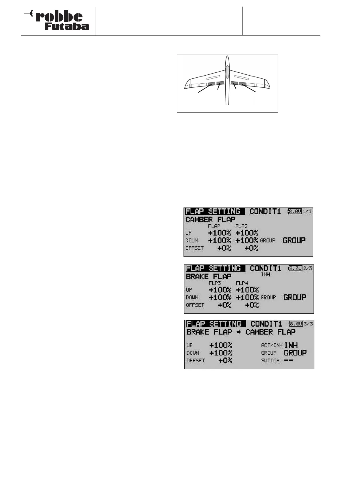
14.2 FLAP SETTINGS
This menu is
used for ente-
ring the set-
tings for all the
i
nboard wing
flaps. If your
model features
two pairs of
inboard flaps
(the most com-
plex available - see diagram above) this menu applies to the
inboard brake flaps and camber-changing flaps, which are
located adjacent to each other. The ‘up’ and ‘down’ travel of
e
ach control surface can be set individually at this point, while
the Offset function allows you to fine-tune the travels. As with
many functions, it is also possible to determine whether the
settings are to apply to all flight modes (Global) or only to the
currently activated flight mode (Separate). If you wish, you can
program a mixer which causes the camber-changing flaps to
be deployed when the brake flaps are operated.
Use the 3-D hot-key to mark the ‘Flap settings’ option in the
Model menu, and confirm your choice with EDIT. This menu
has three levels (pages) which look like this:
You can adjust the travel individually for each control surface
and each direction of movement, using the method already
described repeatedly in this manual. The same applies to the
Offset function; the value is simply entered as a percentage
using the ‘3-D hot-key’.
The effects and methods of setting the ‘Global’ and ‘Separate’
modes have already been described several times. The brake
flap mixer (BrFl -> flap) causes the camber-changing flaps to
follow the movement when the brake flaps are deployed. You
can also set the degree of following for each direction of travel
separately, program an Offset, set the flight mode and pro-
gram a switch.
48
Brake
flap
(
BRF2)
C
amber-
changing
f
lap
(Camber2)
C
amber-
changing
f
lap
(Camber)
Brake
flap
(
BRFL)