Order No.
35 MHz: F 8042
40 MHz: F 8043
41 MHz: F 8044
FX-30
76
ver battery; a separate battery is essential. Be sure to use pro-
perly suppressed spark plugs, plug caps and shielded ignition
cables. Keep the receiving system as far away as possible
from any ignition system.
19.5 RECEIVER BATTERY CAPACITY / OPERATING TIMES
This rule applies to all types of battery: at low temperatures
b
attery capacity is severely reduced, i.e. safe operating
times are shorter in cold weather.
The safe operating time varies greatly according to the number
of servos connected to the receiver, the stiffness of the linka-
ges, and the frequency of control commands generated by the
pilot or operator. A standard servo draws between 150 mA and
600 mA when the motor is running, and about 8 mA at idle.
Super-servos and powerful digital units can draw peak cur-
rents of up to 1300 mA at full power.
Be sure to select a receiver battery with ample capacity,
bearing in mind the likely current drain and the number of
servos in the model.
Ensure that all mechanical linkages are free-moving, and that
the servo is not obstructed in its travel. A servo running con-
stantly against a mechanical stop or limit draws a very high
current, and will also inevitably suffer damage in the long-term.
You will notice the point where the receiver battery is almost
discharged, because the servos will respond much more
slowly than normal. The moment you realise this, land the
model immediately and recharge the battery.
We recommend the use of a battery controller to monitor the
receiver pack during a session, as this gives you a useful idea
of the state of charge of the battery between flights.
19. THE SYSTEM IN USE
All robbe-Futaba receivers continue to work with full range at
reduced voltage, down to the point where the supply voltage
falls to 3 V. The advantage of this feature is that the receiving
system will normally continue to work even if one cell fails
completely (short-circuit), since robbe-Futaba servos still work
d
own to 3.6V, albeit at slightly lower speed and with reduced
power. This is very important in Winter, when ambient tempera-
tures are very low, otherwise any momentary voltage collapse
could cause the loss of a model.
However, there is a drawback: under certain circumstances the
user may not even notice the failure of a battery cell. For this
reason it is important to check the receiver battery from time to
time.
W
e especially recommend the use of robbe battery monitors,
No. 8409, which indicate the condition of the battery by means
of a chain of LEDs.
19.1 POWER-ON SEQUENCE
Always switch the transmitter on first, and only then the recei-
ver; reverse the sequence when switching off. When you
switch the receiver on, the servos run to the neutral position.
We recommend that you check each function in turn by opera-
ting the associated stick or other transmitter control. Check
that each control surface operates in the correct “sense” (dire-
ction) relative to the stick movement. If any control surface
moves in the wrong direction, that servo must be reversed at
the transmitter.
19.2 ‘ELECTRICAL NOISE’ INTERFERENCE
If your radio control system is to operate safely and reliably, it is
essential to avoid what is known as electrical ‘noise’ interfe-
rence. This problem is due to metal parts - such as pushrods -
rubbing against each other intermittently as a result of vibra-
tion. For this reason the linkage to the engine’s carburettor
must always terminate in a plastic clevis - never connect a
metal linkage directly to the carburettor arm without an insula-
tor between them.
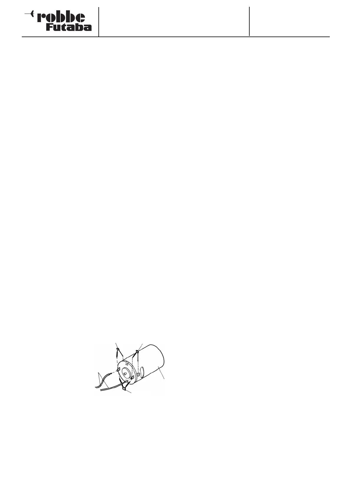
19.3 ELECTRIC MOTORS
All conventional electric
motors in RC models
must be effectively sup-
pressed, otherwise the
sparks which are genera-
ted between the armature
and the carbon brushes
when the motor is running
will have a serious
adverse effect on the
radio control system, i.e.
they cause interference. We recommend robbe suppressor fil-
ters, No. 8306, 8307 or a set of suppressor capacitors, No.
4008. Each electric motor in the model must be suppressed
individually as shown in the diagram.
19.4 ELECTRONIC IGNITION SYSTEMS
The ignition systems of spark-ignition petrol engines can also
generate interference, which has an adverse effect on the radio
control system. Never power an ignition system from the recei-
47 nF
100 nF
Electric
motor
Power con-
nections
100 nF