Order No.
35 MHz: F 8042
40 MHz: F 8043
41 MHz: F 8044
FX-30
14.13 BRAKE FLAP MIXER
(only available if suitable model type is selected)
The purpose of
this menu is to
set the travels
for all wing and
tail control sur-
f
aces in such a
way that the
model’s air-
speed is redu-
ced, but at the
same time the
wing geometry
generates the
required high lift
f
or slow flying.
In basic terms
all the wing control surfaces deflect down, while a correspon-
ding elevator travel compensates for the pitch trim change
(around the lateral axis), which generally accompanies such a
configuration.
An Offset value can be entered separately for all the wing-
mounted control surfaces, i.e. up to four ailerons and four
flaps (screens 1 to 3). You can also assign one of the auxiliary
transmitter controls for fine-tuning the system. This allows you
to set up a pre-set position for all the control surfaces prior to
fine-tuning in flight. As with all mixers, you can select ‘Global’
or ‘Separate’ mode as desired.
A trigger switch can be defined which is used to activate the
settings for the flight phase. You can also determine whether
the mixer is to be activated using the selected switch, or auto-
matically by the position of one of the sticks.
It is possible to set the required transit speed individually for
the aileron servos, flap servos and elevator servos, with sepa-
rate settings for the ‘there’ and ‘back’ directions. If you wish,
you can program a delay time for this mixer function, so that
the transition is smooth rather than abrupt.
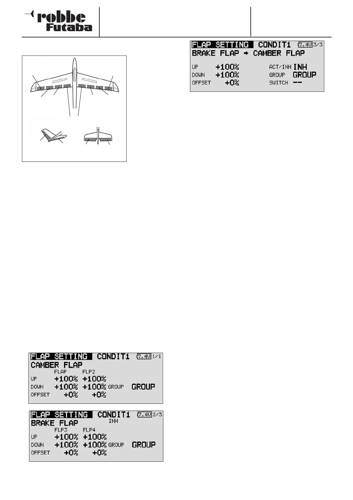
Start by marking the ‘Brake flap’ option in the Model menu
using the 3-D hot-key, and confirm your choice with EDIT. The
menu has several levels (pages), which look like this:
The page indicator on the right-hand side indicates the menu
level in which you are currently working. In the first three
menus the settings are virtually identical; the difference bet-
ween them is that the topmost level contains the settings for
the ailerons, the second page those for the camber-changing
and brake flaps, and the third screen the settings for the ele-
vators.
The brake flap mixer must first be activated in the ‘ACT / INA’
line on the fourth screen. The effects and settings for the pro-
gramming of ‘Global’ or ‘Separate’ mode are entered in the
‘Mode’ line. In the ‘Switch’ line a switch can be selected in the
familiar manner, and its direction of operation determined. The
default setting here is ‘NONE’, i.e. the mixer is always swit-
ched on.
You can also determine whether the ‘Brake flap’ mixer is to be
activated using the selected switch, or by the position of a
stick. The servo transit speed for all three control surface types
(ailerons, flaps and elevator) can be programmed on the fourth
page of the menu, in each case separately for the servo dire-
ctions ‘there’ and ‘back’.
In the last menu display you can select a transmitter control for
fine-tuning the function. It is also possible to program a delay
time. For the brake flap mixer a switch can be defined which,
like the two Trim mixers, is used to switch the delay from acti-
ve to disabled. The complete procedure for programming this
mixer is almost identical to that for setting the two Trim mixers,
so please read about this menu for a fully detailed description:
see Section 14.12 on page 54.
Please note that the programming options and the actual
appearance of the screen displays may vary slightly according
to the model type and the wing type you have selected.
57
Chip
aileron
(AIL3)
Main
aileron
(AIL1)
C
amber-
changing
flap
(CAMBER1)
C
amber-
changing
flap
(CAMBER2*)
Brake flaps
(BRFL3 & 4)
Main
aileron
(AIL2)
Chip
aileron
(AIL4)
V-tail Ailvator
ELE
ELE
RUDD
ELE2