Order No.
35 MHz: F 8042
40 MHz: F 8043
41 MHz: F 8044
FX-30
• Trim Mode
Once you have marked and confirmed this field, you can
set any of the following trim modes by turning the ‘3-D hot-
key’.
Normal = Normal trim type; the trim range is symmetrical
around the servo centre-point. The selected (fixed) trim
range is offset around the centre, which causes changes to
the end-point values.
A
TL = Asymmetrical trim type; the trim value alters only at
one end of the transmitter control range. This is usually
employed for the throttle function, so that you can fine-trim
the idle without affecting the full-throttle position.
CTRM = Centre trim; this trim function also affects the
centre range of the transmitter control, but has no effect on
the end-points. Since the end-points are fixed, the trim tra-
vels change (i.e. become asymmetrical) if you alter the trim
value.
• Global or Separate mode
The ‘Global’ and ‘Separate’ fields determine whether the
trim controls are to be the same for this function in all flight
modes (Global). If you change this function to ‘Separate’,
the trim control for this function can be different for each
flight mode. Turn the ‘3-D hot-key’ to left or right to chan-
ge this setting. The display changes when you operate the
selected flight mode change-over switch.
Note:
Changing the trim from Global to Separate makes it possible
to alter the configuration of various trim controls to suit each
flight mode; it also enables the user to set and store different
trim values for each flight mode.
Typical applications:
1. Different trim controls for each flight mode
In the Normal flight mode the trim controls T1 + T4 are
assigned to control functions J1 + J4. In the ‘Aerobatics’
flight mode the trim controls T1 + T4 are assigned in rever-
se (cross-trims). This makes it possible to control the func-
tion with the one hand, and adjust the trim for the same
function with the other hand.
2. Different trim values for each flight mode
Model helicopters: it can be highly advantageous if the dif-
ferent trim values for the static flight mode ‘Hover’ and the
dynamic flight mode ‘Aerobatics’ can be set and stored
separately.
VIRTUAL CHANNELS: this set-up menu is used to configure
the virtual functions VC-1 … VC-4. The term ‘virtual function’
is used to describe functions which use other channels as
‘double functions’, i.e. they do not have their own servo chan-
nels.
A virtual channel is a separate second control curve with which
a transmitter control affects the servo output.
Examples of this are the Crow (Butterfly) function, which con-
trols the aileron and flap servos, or the elevator function of a
flying wing model, where the ailerons have a dual function,
‘doubling up’ as elevators.
The servo sequence tables (Sections 5.1 to 5.4) on pages 14
to 17 include the virtual functions.
SWITCHED CHANNELS 9 + 10 AND 13 + 14
The switched channels 9 + 10 in PCM 1024 mode, and 13 +
14 in PCM G3 mode, are operated using the transmitter con-
trols DG1 + DG2.
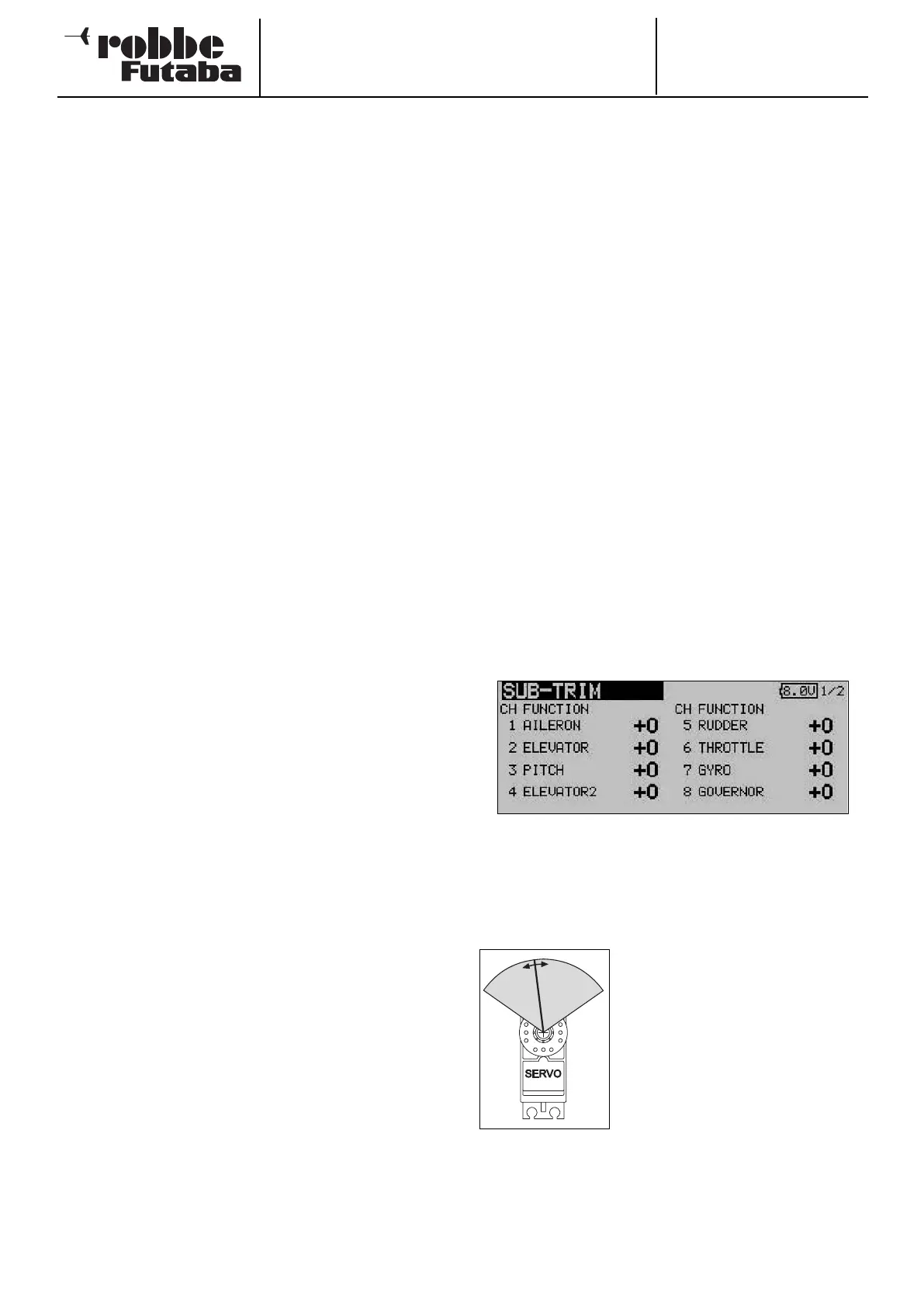
12.6 SERVO CENTRE OFFSET
When you install the servos in a model, it is always best to
position them in such a way that the servo output arm is in the
neutral position when the associated trim control on the trans-
mitter is also at centre.
Sometimes the design of the model makes this impossible,
and in other cases the neutral position is non-standard due to
the use of different makes of servo. In such instances this
function can be used to bring the servos of all channels to the
exact neutral position.
This option should only be used to correct minor discrepan-
cies, as it inevitably affects servo travel, which may become
r
estricted and asymmetrical.
We recommend this procedure:
After establishing the correct trim positions through test-flying,
the first step should be to adjust the position of the servo out-
put arms as accurately as possible, and adjust the control sur-
face linkages to the correct mechanical trim settings. At this
stage the trim memory and the settings in this menu should be
left at 0%. Once you have made these adjustments as accura-
tely as possible, you should use this menu to fine-tune the
servo neutral positions to exact centre.
Note:
Always determine the correct direction of servo rotation (servo
reverse) before adjusting the servo centre offset; see page 33.
Use the 3-D hot-key to mark the ‘Servo centre’ function in the
Base menu, and confirm your choice using EDIT.
This menu has a second level (page) for channels 9 to 12; the
page number on the right-hand side indicates this.
The servo positions are always displayed as a value and as a
%-value.
To change a setting the appropriate
channel must first be marked with the
cursor. Select the correct channel,
then adjust the trim increments by
rotating the 3-D hot-key. The adjust-
ment range is -240 increments to +240
increments, corresponding to around
+/- 20° of servo travel. The default set-
ting is 0 increments.
You can change any active setting back to the default value (0
increments) by holding the 3-D hot-key pressed in for at least
one second.
32