Order No.
35 MHz: F 8042
40 MHz: F 8043
41 MHz: F 8044
FX-30
15.3 ACCELERATION FUNCTION
The purpose of this function is to prevent unwanted changes
in the helicopter’s attitude when you alter the throttle setting or
the collective pitch function. The action of the Acceleration
function is as follows: when you alter the throttle setting, the
software superimposes a temporary compensatory effect. The
result is that rotor speed does not collapse if you suddenly
i
ncrease the blade pitch angle, and rotor speed does not
increase if you suddenly reduce collective pitch. This option
has proved to be extremely useful for general flying, and for 3-
D aerobatic flying in particular.
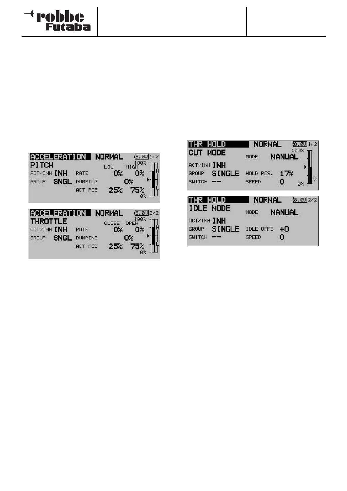
Use the 3-D hot-key to mark the ‘ACCELERATION’ option in
the Helicopter Model menu, and confirm your choice with
EDIT. The screen has two levels (pages), which look like this:
You will now find two strictly separated pages for the collecti-
ve pitch and throttle settings. On the first page you enter a set-
ting for the collective pitch function, and on the second page
a setting for the throttle function. Both settings are entered
using the identical procedure, with the exception that the
terms ‘Min.’ and ‘Max.’ on the collective pitch settings page
are replaced by ‘END’ (idle) and ‘OPEN’ (carburettor open) on
the throttle page, referring to the state of the carburettor. The
following description therefore covers both menu pages, but
we will concentrate on the collective pitch settings in our
example.
The first step is to activate this option in the ‘ACT / INA’ line in
the standard fashion. After this you can select ‘Global’ or
‘Separate’ mode.
You can now enter separate percentage values (Rate) for the
positions ‘Min.’ and ‘Max.’, and ‘END’ and ‘OPEN’. Mark the
field and enter the setting using the ‘3-D hot-key’, then con-
clude the procedure with EDIT. The selected setting is dis-
played as a percentage value in the field, and also in graphic
bar-form. You can enter a percentage value (actually a time
period) in the ‘Damping’ field; this determines how long the
function is to remain active once the change in setting has
been carried out. In the bottom line ‘ACT-POS’ you can define
a point for both sides which represents the position from
which the function is to take effect.
If you decide to make use of this facility, please ensure that the
throttle and collective pitch linkages have sufficient freedom of
movement, i.e. that they are not mechanically restricted or
obstructed at any point. If necessary, adjust the mechanical
linkages until this is the case.
15.4 AUTO-ROTATION SETTINGS
This option is used for entering the settings for auto-rotation,
so that the motor either stops or idles when the ‘Auto-rotation’
flight mode (HOLD) is selected, regardless of the position of
the throttle stick. Two independent settings - idle (IDLE mode)
a
nd motor off (OFF mode) - can be entered. It is advisable to
use the ‘Idle’ mode for practising auto-rotation landings. Either
of the auto-rotation modes can be activated using switches
which you can select without restriction.
Use the 3-D hot-key to mark the ‘AUTO-ROTATION’ option in
the Helicopter Model menu, and confirm your choice with
EDIT. The screen has two levels (pages), which look like this:
You will now find two separate pages for the auto-rotation set-
tings, i.e. ‘motor stopped’ and ‘idle’. On the first page you can
enter the settings for a cut (stopped) motor, while the second
page contains those for the motor at idle. Both sets of values
are entered in exactly the same way. The only item which dif-
fers is the term ‘Auro POS.’ for motor cut, which changes to
‘Idle OFS.’ for the idle option; the first screen also displays the
Offset point for automatic mode in graphic bar-form. The fol-
lowing description therefore covers both menu levels, but we
will concentrate on the ‘Motor off’ mode in the following exam-
ple.
The first step is to activate this option in the familiar fashion in
the ‘ACT / INA’ line. After this you can select ‘Global’ or
‘Separate’ mode.
You can now enter the Auto-rotation mode in the second line.
Two different modes are available:
• Manual: Manual mode
• Auto: Automatic mode
In manual mode the auto-rotation flight mode is only triggered
when you operate a (freely selectable) switch. In automatic
mode, the auto-rotation flight mode is triggered by the position
of the throttle stick. In the latter case it is necessary to define
the trigger point: move the throttle stick to the desired posi-
tion, then press the ‘EDIT’ button. The trigger position is dis-
played in bar-form on the right of the screen.
65