Order No.
35 MHz: F 8042
40 MHz: F 8043
41 MHz: F 8044
FX-30
13.2 TRANSMITTER CONTROL TRAVEL SETTINGS
The transmitter control travel (AFR) settings are used to adjust
the travel characteristics (Expo1, Expo2, Curve) which a trans-
mitter control employs when it affects the associated receiver
output (servo) or mixed functions.
Sixteen AFR curves are available in total: twelve transmitter
controls for the twelve servo channels and four VC transmitter
c
ontrol curves for the virtual channels, whose transmitter con-
trols have no direct servo output; instead they control servos
using a supplementary curve, according to a mixed function.
Summary:
Eight flight modes with up to twelve transmitter control curves
plus four VC curves, plus six switchable (D/R) curves. It is diffi-
cult to imagine a more convenient system.
Each curve can have two to seventeen curve points, plus a
v
ariable speed which is set separately. All the adjustments can
be carried out for each function individually.
Note:
It is essential to complete the following settings before car-
rying out adjustments to the transmitter control curves:
1) Model type select
2) Servo and function sequence
3) Direction of servo rotation
4) Servo travel (ATV)
5) Servo centre
The reason for this requirement is that any change to the func-
tion sequence, for example, erases any curve which has alre-
ady been set.
Use the 3-D hot-key to mark the transmitter control travel
(AFR) function in the Model menu, and confirm your choice
with EDIT.
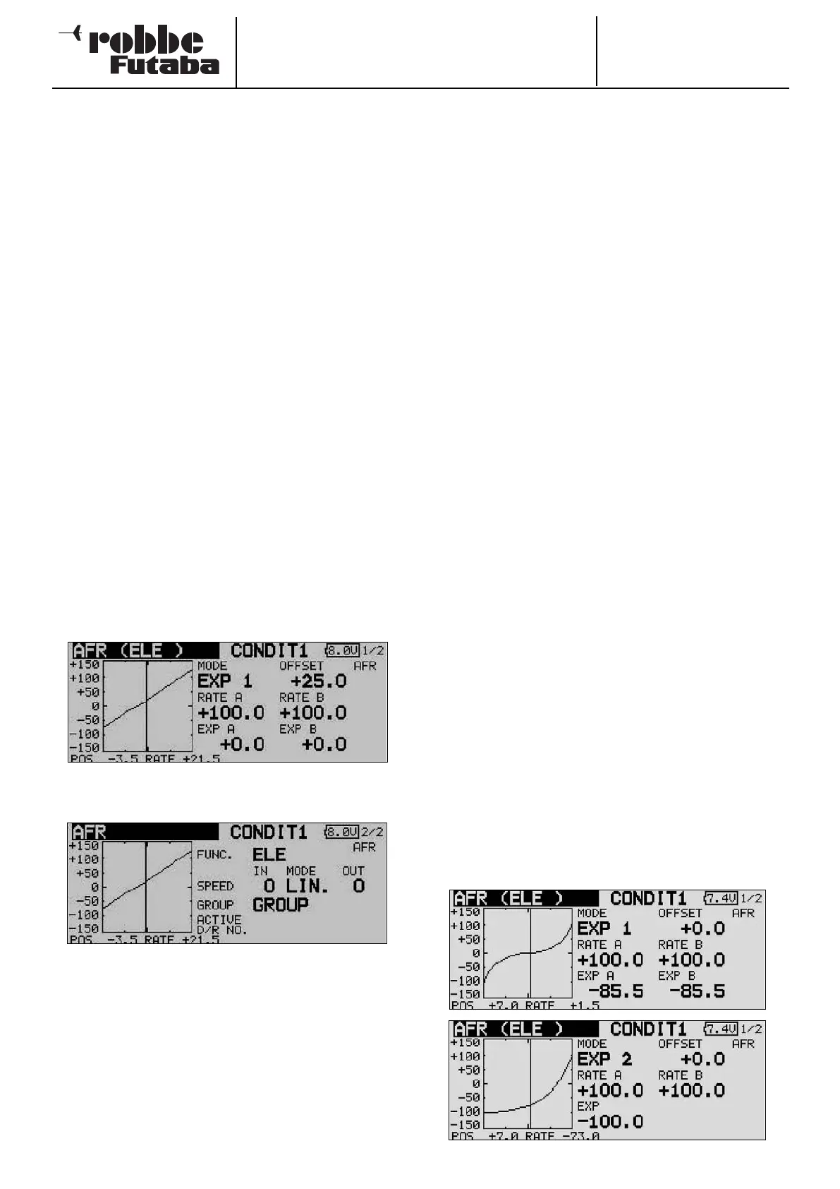
The screen display now looks like this:
This display has two levels (pages); the page indicator on the
right-hand side indicates this. The second page looks like this:
Operation:
• Entering pre-set values
First use the 3-D hot-key to mark the set-up field on the
second page (FUNCT). Turn the ‘3-D hot-key’ to select the
transmitter control whose settings you wish to adjust.
At this point you can also define whether the settings you
are about to enter apply to all flight modes (Global) or only
to one specific mode (Separate). Turn the ‘3-D hot-key’ to
change this setting, and confirm with the ‘EDIT’ button.
In this menu the servo speed can also be adjusted in the
‘Speed’ field. The first facility at this point is to program a
mode (linear or non-symmetrical). The linear mode is used
to control the throttle servo and for switches; this mode is
not self-neutralising. This characteristic applies to the
other, non-symmetrical mode, which for this reason is the
d
efault setting for all control surfaces.
If you wish, you can enter a separate speed for both dire-
ctions (‘there’ and ‘back’). The adjustment range is 0 to 27
increments. Please note: the higher the number, the more
slowly the servo moves. The maximum value (27 incre-
ments) corresponds to a duration of nine seconds. The ‘3-
D hot-key’ is used to alter the setting. The default setting is
always ‘0’. Holding the ‘EDIT’ button pressed in for at least
o
ne second restores the default setting.
• Programming curves
• The first step in this process is to determine the curve type.
Starting from the main display, mark the ‘MODE’ field and
use the ‘3-D hot-key’ to make your selection. The following
curve types are available:
EXP1: Exponential curve (curve 1)
EXP2: Exponential curve (curve 2)
CURVE: 9-point curve (2- … 17-point) curve with
turn-points
Press the ‘EDIT’ button to activate the selected curve type and
display it in graphic form.
• The settings can be defined separately for the right side
(RATE A) and the left side (RATE B) of the curve: mark the
appropriate field and use the ‘3-D hot-key’ to alter the
value in it. The adjustment range is -200% to +200%; the
default setting is +100%. Holding the ‘EDIT’ button pres-
sed in for at least one second restores the default setting.
• The curve can be shifted vertically (OFFSET). This is
accomplished by marking it with the ‘3-D hot-key’ and
confirming with EDIT. Positive values move the curve up;
negative values down.
The same procedure is employed for setting up the two availa-
ble exponential curves. The illustrations show two typical
examples of these curve types. The EXP function affects the
characteristics of the primary sticks: the linear connection bet-
ween the transmitter control travel and the servo travel is alte-
red to an exponential characteristic, which generally provides
finer control of the model.
As an additional feature, the fields ‘Rate A + B’ can be marked
to adjust the transmitter control travel separately for each side
of centre.
42