Order No.
35 MHz: F 8042
40 MHz: F 8043
41 MHz: F 8044
FX-30
• Selecting the switch
With the timer configured in this way, you can move on to
defining the switches which are to be used to control the
timers. In each case a switch can be assigned for:
- Resetting the timer (‘Reset’),
- Starting the timer,
- Stopping the timer, and
- Recording lap times (split time).
The same switch can also be assigned to individual timer
function options. In each case mark the field adjacent to the
switch list, operate the ‘EDIT’ button and determine the
desired switch and direction of operation in the Switch
Select menu.
A timer can be reset by operating the switch defined for that
purpose. However, an alternative method is to activate the
‘Reset’ field of the corresponding timer function, and then
press the ‘EDIT’ button.
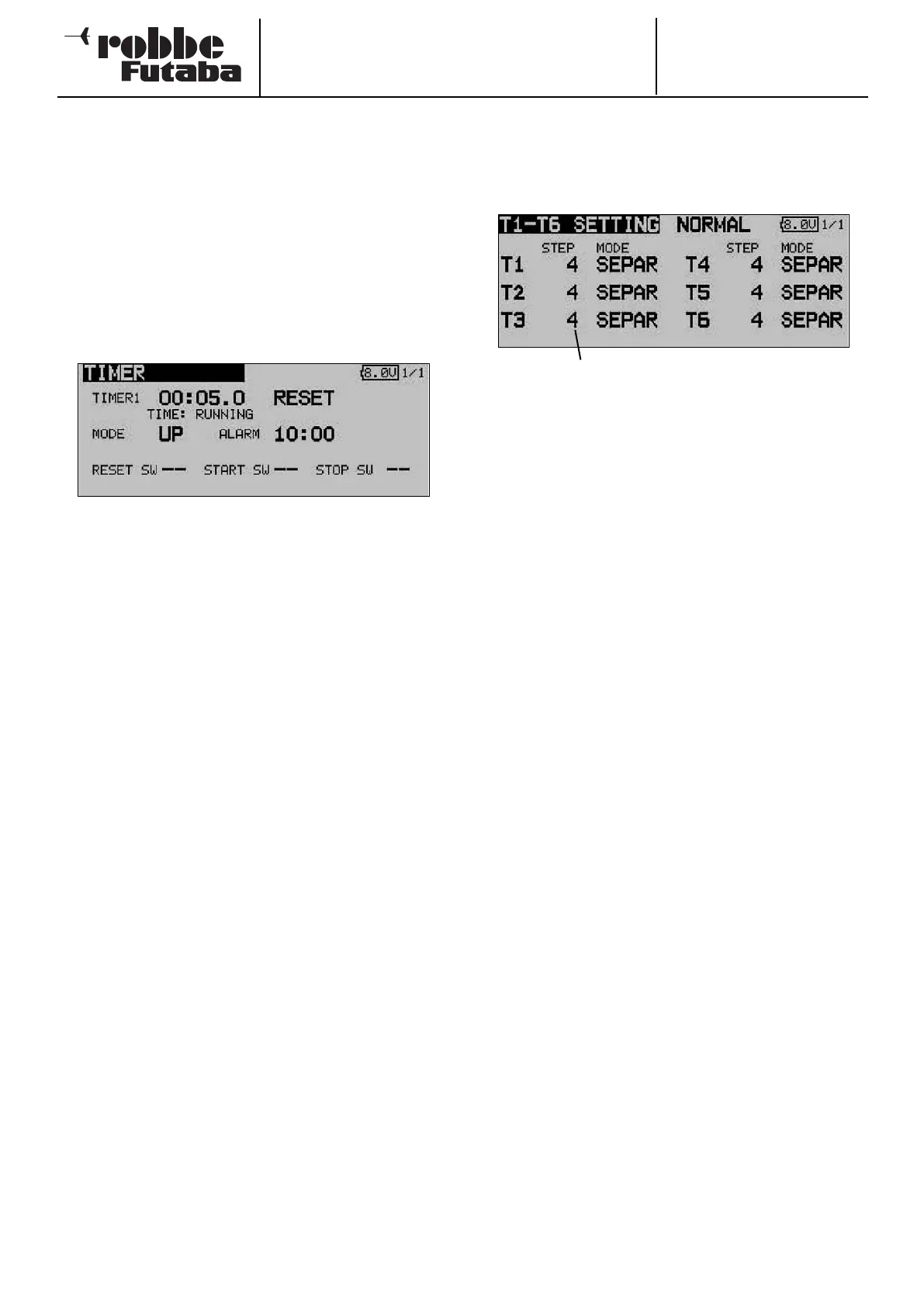
12.15 TRIM DISPLAY
Use the 3-D hot-key in the Base menu to mark the “Trim dis-
play” function, then confirm your choice with EDIT. The screen
display now looks like this:
The current settings are now displayed in the form of an incre-
ment (step) value for the trim buttons T1 … T6. You can also
select the ‘Global’ or ‘Separate’ mode for the trim buttons.
The Step setting provides a means of adjusting the resolution
of the trims. The resolution is variable within the range 1 …
200; at the finest resolution even the most minute of inaccura-
cies can be trimmed out. The default increment value is 4,
which gives a resolution of -50 and +50 increments. Changing
the increment value to 8 produces a resolution of -25 and +25
increments.
The higher the value, the ‘coarser’ the trim resolution.
The settings can either be adopted for all flight modes
(Global), or just for the selected flight mode (Separate).
38
Trim increment indicator