Order No.
35 MHz: F 8042
40 MHz: F 8043
41 MHz: F 8044
FX-30
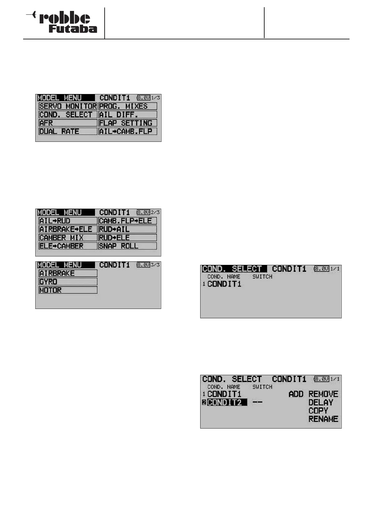
13. MODEL MENU
The Model menu, which is described in detail in this section,
provides functions which enable you to enter wide-ranging
settings for a specific model memory. The data is then stored
under the programmed model name in the appropriate model
memory.
Since a single display cannot encompass all the functions
which are available in the Model menu, there are two additio-
nal display pages in which the remaining functions can be
selected. The page indicator on the right-hand side of the
screen indicates that more data is available on additional
pages. Individual menu points are selected by operating the
S1 button. The sub-menus are listed below.
The following options - amongst others - are available accor-
ding to the selected model type:
• SERVO MONITOR Servo travel display
• FLIGHT MODE: Flight mode select
• CONTROL AFR: Transmitter control travel settings
• DUAL RATE: Switchable second control curve
• PROG. MIXER: Programmable mixers
• AIL DIFF: Aileron differential
• FLAP SETTING: Flap travel setting
• AIL TO FLAP: Aileron -> flap mixer
• AIL TO RUD: Aileron -> rudder mixer
• Airbrake to elevator: Airbrake -> elevator mixer
• AILERON -> spoiler: Aileron -> spoiler mixer
• AILERON -> brake flap: Aileron -> brake flap mixer
• Flap -> elevator: Flap -> elevator mixer
• Rudder -> aileron: Rudder-> aileron mixer
• Rudder -> elevator: Rudder -> elevator mixer
• SNAP ROLL: Snap roll function
• Spoiler: Brake flap mixer
• Mixture adjustment: Carburettor mixture adjust
• Gyro: Gyro adjustments
• V-tail: V-tail mixer
Note:
The following section does not describe every possible option,
as some of them have already been discussed in previous
menus, or are described in the next section which covers the
model type menus; these menus can also be activated at that
point. The displays for the individual options may vary slightly
according to the model type you have selected.
13.1 FLIGHT MODE
The software of the FX-30 provides up to eight flight modes for
each individual model memory. This feature ensures that you
can always store the optimum settings for the various phases
of a typical flight, and call them up as and when required sim-
p
ly by operating a switch.
For example, this option can be used to program the settings
for a model glider so that the control surfaces are set correct-
ly for the winch launch phase, i.e. both ailerons and both flaps
lowered in order to gain maximum possible lift for the launch.
To guarantee a stable flight attitude you could also select the
option for setting an elevator offset to provide pitch trim com-
pensation (around the lateral axis). These values can be called
u
p prior to launching the model, using a switch or a particular
position of one transmitter control.
If you program several flight modes in a particular model
memory, it is possible to define the priority of the modes in any
way you like. Flight modes can be copied, named and rena-
med individually, and also erased individually. You can pro-
gram a delay time for each channel, so that there is a smooth
transition when you switch modes, rather than an abrupt
change.
Use the 3-D hot-key to mark the ‘Flight mode’ option in the
Model menu, and confirm your choice with EDIT. The screen
display now looks like this:
The basic programming procedure consists of the following
steps:
• Adding a new flight mode
Use the 3-D hot-key to mark the ‘New’ field, and confirm
your choice with the ‘EDIT’ button. The screen now shows
the next available number which can be allocated for the
new flight mode. Pressing the ‘EDIT’ button again calls up
the new flight mode on the screen.
Mark the field for selecting the flight mode switch (--), and
press the ‘EDIT’ button to call up the Switch Select menu.
In this sub-menu you can define the flight mode activation
switch, and its mode of operation, i.e. the direction for acti-
vating and disabling the new flight mode.
Note that it is possible to select an individual switch (SINGLE)
or a logically linked pair of switches (LOGIC).
40